
Can You Use the Same Magnetic Ring with Different Encoder ICs?
A practical compatibility guide for iC-MU, iC-MUE, NSM350x and MLX90384 designs.
Updated 22 Nov 2026 · Pole geometry, magnetic input and qualification
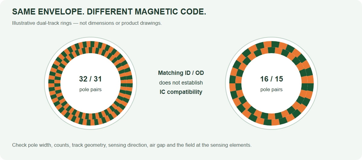
Pole width, pole-pair pitch and air gap are different dimensions
First agree what a supplier means by “pole pitch.” In this article, w is the width of one N or S pole along the specified scan track; λ is one complete N/S pair period, equal to 2w. The 1.28 / 1.50 / 2.00 mm iC-MU target classes refer to master-track single-pole width. They are not sensor-to-magnet air gaps.
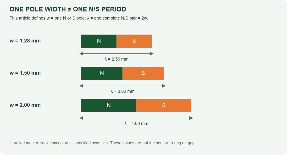
Swipe to view the complete pole-width diagram →
For a uniformly magnetised circular scan track with N pole pairs:
For 32 pole pairs, the ideal master scan diameters are approximately 26.08 mm at w = 1.28 mm, 30.56 mm at 1.50 mm, and 40.74 mm at 2.00 mm. Scan diameter is not the physical ring OD. Track width, edge margin and the carrier add separate dimensions.
Why fixed Hall-array geometry sets the magnetic target pole pitch
In a fixed-pitch off-axis encoder IC, the Hall sensing elements are manufactured at fixed physical positions on the silicon. As the magnetic pattern moves past the array, these positions sample different phases of its spatial field waveform. The IC combines the samples to form sine and cosine signals, then interpolates their phase into position.
The target wavelength must match the array geometry specified for that IC. If the magnetic period changes while the sampling positions stay fixed, the phase relationships change. Channels intended to form quadrature signals can acquire phase, gain and waveform errors, reducing interpolation accuracy or preventing reliable decoding. A similar ring OD does not correct this mismatch.
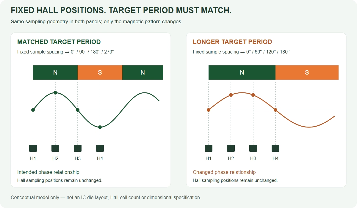
Swipe to compare the two sampling patterns →
Simplified sampling model: the illustration explains spatial phase, not the actual Hall-cell count, die layout or manufacturing dimensions of any named IC. Actual array arrangements and signal combinations are device-specific.
iC-MU: use the exact device’s width
For the legacy iC-MU / iC-MU128, the specified master single-pole width is 1.28 mm, corresponding to a 2.56 mm N/S period. The required width follows the Hall-array geometry. The family also includes iC-MU150 at 1.50 mm and iC-MU200 at 2.00 mm: 1.28 mm is not a universal value for the entire series.
MT6620: 2 mm poles, 4 mm pairs
MagnTek MT6620 integrates a fixed 2 mm-pitch Hall array. Its datasheet requires a 2 mm single-pole pitch magnetic scale or ring, equivalent to a 4 mm complete pole-pair period. Match that specification when designing the magnetic target; changing mechanical diameter alone cannot adapt a different pole width.
The master track is also the system reference
In a multi-track absolute encoder, the master track supplies the fine periodic position and a reference for combining the tracks. The nonius track and configured pole-pair relationship resolve which master period is being read. Master pole-width uniformity, scan radius, track alignment and relative phase therefore affect the complete absolute-position result. Design both tracks together, rather than selecting their widths independently.
The specified pole width is a nominal design requirement, not a claim of zero manufacturing tolerance. Check the allowed magnetic and assembly tolerances, field waveform and calibration procedure for the exact part. Geometry-flexible architectures such as iC-MUE and pitch-independent MLX90384 have different capabilities; apply their own target rules rather than extending this fixed-pitch example to every off-axis IC.
Magnetic ring pole-pitch requirements by encoder IC
The table uses the definitions above. It groups nominal target classes; it does not certify an existing ring or establish PCB, pinout or firmware compatibility.
Swipe horizontally for the complete compatibility table →
| Encoder IC | Master single-pole width w | Full N/S period λ | Target-selection rule |
|---|---|---|---|
| iC-MU128 | 1.28 mm | 2.56 mm | 16/15, 32/31 or 64/63 master/nonius pairs; use its 1.28 mm target geometry. |
| iC-MU150 | 1.50 mm | 3.00 mm | Same supported pair-count classes; different scan geometry from the 1.28 and 2.00 mm variants. |
| iC-MU200 | 2.00 mm | 4.00 mm | 16/15, 32/31 or 64/63 reference targets; verify the 4.0 mm sensor-array track separation. |
| iC-MUE | Optimised for 2.00 mm | 4.00 mm for the nominal 2.00 mm class | Geometry-flexible Nonius engine. Qualified iC-MU200-style targets can be shared; not every FlexCode target is backward-compatible. |
| iC-MU, legacy part | 1.28 mm | 2.56 mm | Legacy iC-MU is the 1.28 mm device. “iC-MU Series” can also refer to the broader family: check the exact part number. |
| NSM3500 | 1.28 mm | 2.56 mm | Requires a 1.28 mm master single-pole width; check the complete target drawing and exact device variant. |
| NSM3501 | 1.50 mm | 3.00 mm | Requires a 1.50 mm master single-pole width; check the complete target drawing and exact device variant. |
| NSM3502 | 2.00 mm | 4.00 mm | Reviewed CN 0.2 datasheet: 16, 32 or 64 master pole pairs; compare its full master/nonius geometry. |
| MLX90384 | Pitch-independent; no fixed 1.28 / 1.50 / 2.00 mm selector | Target-specific | Use the specified Vernier magnet, sensing positions and system software. Reference magnet sets use 8/7 or 14/13 pairs. |
For the wider electronic comparison, see NSM3502 / NSM350x versus iC-MU encoder selection. For available target geometries, compare our standard iC-MU magnetic rings and encoder discs.
Why the same ring size does not mean interchangeable magnetic encoding
Same ID/OD, different magnetic period
A mechanically identical carrier can be magnetised with a different pole count or pole width. A fixed Hall-array geometry may then scan the wrong electrical period, even though the ring bolts into the same housing.
Same master pole width, different second track
The nonius track must deliver the intended relative phase and count relationship at its own scan radius. Matching only the master width leaves track spacing, polarity and absolute-angle decoding unresolved.
The iC-MU reference rotary targets use N master pairs and N−1 nonius pairs: commonly 16/15, 32/31 or 64/63. The iC-MU128/150 sensor-array separation is 3.6 mm, while iC-MU200 uses 4.0 mm. Those different geometries cannot be reduced to “two-track ring.”
When can NSM350x and iC-MU magnetic rings be reused?
Start with the corresponding nominal class—NSM3500 with the 1.28 mm class, NSM3501 with 1.50 mm, and NSM3502 with the iC-MU200-style 2.00 mm class. Treat these as candidate pairings until the complete target drawing and magnetic input meet both designs.
| Check | Evidence needed for reuse |
|---|---|
| 1. Pole width and pole pairs | Same definition of w/λ, supported master pair count and the intended nonius pair count. |
| 2. Track relationship | Correct scan diameters, track widths, sensor-array spacing, magnetisation polarity and relative phase. |
| 3. Reading direction | Same active surface and correct magnetic component at the sensing elements. Axial face and radial outer-edge reading are separate designs. |
| 4. Sensing position and gap | Compare the package/die reference, radial and tangential placement, gap datum, eccentricity and runout limits. |
| 5. Magnetic input | Measure both tracks at the intended gap over temperature. Check the relevant field components, amplitude limits, gradients and distortion. |
| 6. Electronics and qualification | Configure pole counts and interfaces, recalibrate, and verify absolute angle, power cycles, direction and dynamic operation against a reference. |
For example, NSM3502 CN 0.2 specifies a 10–125 mT perpendicular input-field range at the chip surface over its stated temperature range. That is not a universal acceptance window for every iC-MU or MLX90384 design.
Reading direction refers to the readhead’s relationship to the ring surface; it must not be inferred only from a magnetisation label. Our axial and radial off-axis encoder selection guide compares the mechanical layouts.
Can iC-MUE and iC-MU200 share the same magnetic ring?
Yes, qualified iC-MU200-style 2.00 mm dual-track targets can be shared with an appropriately configured iC-MUE design. OTV supports this target-reuse route. Confirm the pole-pair combination, both scan tracks, sensing positions and magnetic operating conditions before releasing the design.
This is magnetic-target reuse—not a claim of pin, PCB, EEPROM, interface-timing or firmware interchangeability. iC-MUE’s flexible Nonius engine can support geometries beyond the older device’s reference combinations; that does not make every iC-MUE target automatically suitable for iC-MU200 in the reverse direction.
Review iC-MUE features and matched magnetic rings and send the current target drawing with the proposed replacement IC.
MLX90384: pitch-independent does not mean any magnetic ring
The Melexis datasheet, revision 3.0 dated 13 May 2026, describes a pitch-independent Arcminaxis architecture. It does not assign the IC a fixed 1.28, 1.50 or 2.00 mm master-pole-width class. Its reference magnets, sensing geometry and software remain part of the system specification.
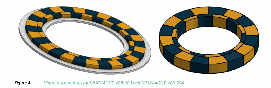
The reference magnet and assembly options
Swipe horizontally for all magnet and gap columns →
| Melexis target | ID mm | OD mm | Thickness mm | Master / nonius pole pairs | Package-top-to-magnet gap mm |
|---|---|---|---|---|---|
| MLXMAGNT-VER-001 | 14 | 24 | 4.5* | 8 / 7 | 1.0–2.0; nominal 1.5 |
| MLXMAGNT-VER-002 | 6 | 24 | 6.0 | 8 / 7 | 1.0–2.0; nominal 1.5 |
| MLXMAGNT-VER-003 | 25 | 42 | 1.8 | 14 / 13 | 1.0–2.0; nominal 1.5 |
| MLXMAGNT-VER-004 | 16 | 24 | 3.5 | 8 / 7 | 0.5–1.5; nominal 1.0 |
Source: Tables 3–4, pp. 4–5, and Tables 14–16, p. 18. * VER-001 thickness excludes the transport holder. Nominal radial sensor-centre positions are 9.5 mm for VER-001/-002/-004 and 16.5 mm for VER-003, with ±0.5 mm tolerance; tangential tolerance is ±0.5 mm in the listed assemblies.
The two sensing spots inside MLX90384 are 1.9 mm apart. This is not a universal track-centre spacing: the datasheet places the master spot above the master-track centre and the nonius spot between the tracks. It measures both axial Bz and tangential Bx components, then uses a microcontroller and the specified software/calibration flow.
Check field components at each sensing spot
These are typical amplitudes at 25°C and nominal assembly position, not generic minimum/maximum operating limits.
| Reference target | Bz, master / nonius spot | Bx, master / nonius spot |
|---|---|---|
| VER-001 / VER-002 | 40 / 16 mT | 33 / 25 mT |
| VER-003 | 27 / 15 mT | 27 / 15 mT |
| VER-004 | 41 / 21 mT | 34 / 16 mT |
Source: Tables 5–7, p. 9. Do not use the ±1 T absolute-maximum rating as a usable encoder input-field specification.
See the official MLX90384 datasheet for the reference drawings and complete assembly requirements.
When must you redesign or re-magnetise the ring?
A new magnetic design is needed when…
- The replacement IC cannot accept the existing master pole width or count combination.
- Master/nonius scan radii, track separation or relative phase cannot match the new sensing geometry.
- The active reading surface or required field direction changes.
- The ring cannot meet both amplitude and waveform requirements at the available gap and temperature.
- A changed bore, carrier or housing removes the usable track area or prevents the required mounting position.
A new ring is not automatic when…
- The existing magnetic target already satisfies both designs’ complete requirements.
- A PCB position, parameter change and recalibration can bring the installation into the validated envelope.
- The requested change concerns only a host protocol or connector that leaves the target requirements unchanged.
Reuse still requires qualification. Calibration cannot correct an incompatible pole pattern or a field outside the supported range.
Distinguish a new mechanical carrier, a new magnetisation program and a new magnetising fixture. They are not the same change. An existing carrier may be reusable while its magnetic pattern must change; whether a finished ring can be re-magnetised safely is a supplier/process decision, not a default assumption.
A practical ring-reuse qualification checklist
- Collect both IC specifications: exact part, package/revision, sensing geometry, field input and intended configuration.
- Audit the target drawing: ID/OD, material, thickness, active surface, both scan diameters, pole counts, widths and phase.
- Measure the installed magnetic field: use the actual sensing positions, gap datums and temperature range—not only a surface-field reading on the magnet.
- Configure and recalibrate: follow the replacement IC’s procedure; do not reuse old EEPROM values without checking their meaning.
- Validate the encoder: sweep a full turn against an independent reference, repeat power cycles and verify alignment, direction, temperature and speed requirements.
For a compatibility review, send the current ring drawing, magnetisation specification, field measurements if available, both IC part numbers, installation drawing, accuracy target and quantity. OTV can review encoder IC supply, standard magnetic targets or a custom magnetic ring design as separate procurement routes.
Start a matched target concept with the OTV magnetic ring designer
Use the OTV Magnetic Encoder Ring Designer to describe an axial or radial reading layout, single- or dual-track coding, ring ID/OD and thickness, and mounting-hole positions. Add the encoder IC, pole-pair count and pole widths so the target concept can be reviewed with the sensor requirements.
The tool provides a live drawing and lets you save the design as JSON, download an SVG or print a draft/PDF. Send the concept for engineering review before manufacture: the preview does not verify field strength, track phase, sensor compatibility or achievable accuracy.
Magnetic ring compatibility FAQ
Can a 1.28 mm ring replace a 2.00 mm ring with the same outside diameter?
Not on dimensions alone. The pole period at the scan track and the IC’s sensing arrangement must match. Different single-pole widths at the same scan diameter imply different pole counts, so the absolute decoding and second-track relationship must be re-evaluated.
Does 2 mm pole pitch mean a 2 mm air gap?
No. Pole width or pitch describes distance along the magnetic pattern; air gap is the separation between the magnet and the sensor’s defined reference surface. Confirm both definitions on the drawings.
Does pitch-independent MLX90384 accept every iC-MU magnetic target?
No. Pitch independence removes a fixed pole-width class; it does not remove the required Vernier relationship, sensing geometry, field components, software support or calibration. The datasheet’s reference target options are the starting point.
Can OTV supply a shared iC-MUE / iC-MU200 target?
Yes. OTV can review a common 2.00 mm-class target for qualified iC-MUE and iC-MU200 designs. Provide the exact track drawing and both assembly requirements; magnetic-target reuse does not establish chip or board interchangeability.
Check the ring before changing the encoder IC
Send the old and new IC part numbers with your magnetic target and mounting drawings. OTV Sensing can help assess reuse, a standard target option or a revised magnetic ring.