
Off-Axis Magnetic Ring Design Guide for iC-MU Encoders
Designing an off-axis magnetic ring starts with the encoder IC, its pole width and the Master / Nonius number of pole pairs. This guide covers dual-track magnetic encoder rings for iC-MU / iC-MU128, iC-MU150 and iC-MU200: calculate scan diameters, check the hollow-shaft mechanical envelope, and plan installation tolerances and calibration.
Technical guide by OTV Sensing · Updated October 25, 2026
Off-axis magnetic ring design: the engineering roadmap
How does an off-axis dual-track magnetic ring work?
An off-axis magnetic encoder reads a magnetized ring away from the shaft center. In the axial face-scanning arrangement covered here, the sensor reads two concentric tracks: a Master track with p pole pairs and a Nonius track with p − 1. Their phase relationship identifies position around one mechanical revolution, while interpolation provides finer output subdivisions.
A ring-shaped target leaves room for a hollow shaft, cable routing or a bearing, but the usable bore must still leave sufficient magnetic material around the inner track. The magnetic encoder ring, also called an encoder magnet ring or magnetic target disc, is one part of the sensing system; resolution is not a guarantee of angular accuracy.
For the complete system and assembly sequence, read how a hollow-shaft magnetic encoder works and how to install it. Use this guide when you need to specify the magnetic target itself.
1. Match a dual-track magnetic encoder ring to the iC-MU IC
The number of pole pairs is a design input, not a label to add after choosing an arbitrary ring diameter. Each IC variant has a specified Master pole width and distance between the two sensor arrays.
| IC variant | Master pole width wM | Master period TM | Array spacing d |
|---|---|---|---|
| iC-MU / iC-MU128 | 1.28 mm | 2.56 mm | 3.60 mm |
| iC-MU150 | 1.50 mm | 3.00 mm | 3.60 mm |
| iC-MU200 | 2.00 mm | 4.00 mm | 4.00 mm |
One pole pair contains one north and one south pole. A 32-pole-pair Master track therefore has 64 alternating poles. For the two-track layouts covered here, the Nonius track has one fewer pole pair: 16/15, 32/31 or 64/63. Confirm the exact chip and hardware revision when releasing the design.
2. Calculate Master / Nonius scan diameters and sensor position
Use p for the Master number of pole pairs, wM for one Master pole width, and d for the sensor-array spacing. Dimensions are in millimeters.
Master scan circle
CM = 2pwM
DM = 2pwM / π
The Master scan circumference contains p complete north/south periods. DM is the diameter through the sensing path, not the target outside diameter.
Nonius scan circle
DN = DM − 2d
The sensor arrays are separated radially by d. Their scan diameters therefore differ by 2d, not d.
Sensor reference radius
= (DM − d) / 2
This locates the geometric midpoint of the two sensing arrays. Transfer that reference to the PCB using the selected package drawing; do not assume every package or board datum is the same point.
Initial target outside diameter
Use this as an initial edge allowance, then review the magnetic material and structure. An extra 3 mm on diameter is approximately 1.5 mm radially outside the Master scan circle. It does not determine the bore, track widths or carrier dimensions.
3. Off-axis magnetic ring diameter calculator
Select the chip and Master number of pole pairs. The calculator uses the equations above; the tables that follow provide the same values for reference.
Values are calculated before rounding. The calculator does not predict magnetic field strength, track-edge effects, achievable accuracy or the complete installation tolerance. Dimensions stay in your browser; this calculator does not submit an inquiry.
4. iC-MU magnetic ring dimensions: 16/15, 32/31 and 64/63 pole pairs
All values are nominal calculations, rounded at the final step. The initial outside diameter is an engineering starting point, not a finished catalog part dimension.
iC-MU / iC-MU128 magnetic ring dimensions
Master pole width: 1.28 mm · Master period: 2.56 mm · Array spacing: 3.60 mm
| Pole pairs Master / Nonius | Master scan DM | Nonius scan DN | Sensor midpoint Rref | Initial target OD DM + 3 | Filtered output* |
|---|---|---|---|---|---|
| 16 / 15 | 13.04 | 5.84 | 4.72 | ≈ 16.0 | 18-bit |
| 32 / 31 | 26.08 | 18.88 | 11.24 | ≈ 29.1 | 19-bit |
| 64 / 63 | 52.15 | 44.95 | 24.28 | ≈ 55.2 | 20-bit |
iC-MU150 magnetic ring dimensions
Master pole width: 1.50 mm · Master period: 3.00 mm · Array spacing: 3.60 mm
| Pole pairs Master / Nonius | Master scan DM | Nonius scan DN | Sensor midpoint Rref | Initial target OD DM + 3 | Filtered output* |
|---|---|---|---|---|---|
| 16 / 15 | 15.28 | 8.08 | 5.84 | ≈ 18.3 | 18-bit |
| 32 / 31 | 30.56 | 23.36 | 13.48 | ≈ 33.6 | 19-bit |
| 64 / 63 | 61.12 | 53.92 | 28.76 | ≈ 64.1 | 20-bit |
iC-MU200 magnetic ring dimensions
Master pole width: 2.00 mm · Master period: 4.00 mm · Array spacing: 4.00 mm
| Pole pairs Master / Nonius | Master scan DM | Nonius scan DN | Sensor midpoint Rref | Initial target OD DM + 3 | Filtered output* |
|---|---|---|---|---|---|
| 16 / 15 | 20.37 | 12.37 | 8.19 | ≈ 23.4 | 18-bit |
| 32 / 31 | 40.74 | 32.74 | 18.37 | ≈ 43.7 | 19-bit |
| 64 / 63 | 81.49 | 73.49 | 38.74 | ≈ 84.5 | 20-bit |
*Resolution is not accuracy. The 18/19/20-bit values assume 14-bit interpolation per Master period with suitable filtering and configuration. At 12-bit interpolation, the corresponding single-turn values are 16/17/18 bits. Output format, filtering, dynamic response and achievable system accuracy must be checked separately.
Worked example: iC-MU200, 32/31 pole pairs
DM = 32 × 2 × 2.00 / π = 40.7437 mm. DN = 40.7437 − 8.00 = 32.7437 mm. Rref = (40.7437 − 4.00) / 2 = 18.3718 mm. The initial target OD is approximately 43.7 mm.
For a 25 mm bore, the Nonius scan circle lies about 3.87 mm radially outside the bore edge. That space still has to accommodate the actual Nonius track width and its inner edge allowance; it is not automatically usable clearance.
5. Fit the encoder magnet ring to a hollow-shaft assembly
A correct pair of scan diameters is only the start of the drawing. Define the mechanical envelope and magnetic target together so that assembly tolerances do not consume the signal margin.
- Bore and shaft interfaceRecord the clear bore, shaft fit, bearing envelope and retention method. Keep the inner magnetic track fully supported with sufficient material between the scan path and the bore.
- Target, carrier and housingSpecify magnetic layer thickness, metal carrier, adhesive or molded bond, mounting holes and the rotating envelope. Keep holes and slots away from active tracks unless the field design accounts for them.
- Air gap and tiltBudget nominal gap, axial runout, bearing motion and thermal movement together. Check the field at the sensing elements over the full range; the chip’s internal sensor depth is not a universal operating air gap.
- PCB and sensor referenceLocate the two sensing arrays relative to the rotation axis. Include PCB placement, package orientation and assembly tolerances. Provide a repeatable datum or an adjustment method for prototype alignment.
- Materials and nearby metalChoose the magnetic compound and carrier for temperature, media exposure and bonding. Review nearby steel, fasteners, motor magnets and other stray-field sources in the assembled geometry.
- Inspection and productionDefine how pole pattern, concentricity, scan-path field and dimensions will be inspected. Retain a validated magnetic ring, PCB configuration and calibration procedure as a matched system.
6. Magnetic ring eccentricity and Nonius phase tolerance
More pole pairs increase the number of fine position periods per turn, but reduce the permitted Master-to-Nonius phase mismatch. A larger scan diameter alone does not guarantee a more accurate or more robust encoder.
| Master / Nonius | MPC setting | Maximum phase deviation* | Referenced disc eccentricity limit |
|---|---|---|---|
| 16 / 15 | 0x4 | ±9.84° electrical | 0.06 mm |
| 32 / 31 | 0x5 | ±4.92° electrical | 0.10 mm |
| 64 / 63 | 0x6 | ±2.46° electrical | 0.10 mm |
Allocate a system error budget
Disc eccentricity, magnetic pattern error, chip placement, tilt, thermal movement and package stress can all affect the two-track phase relationship. The listed eccentricity limit is not a complete tolerance budget or a guarantee that every assembly will synchronize.
Check the entire revolution
Inspect the Nonius error curve across a full turn and over the operating conditions. If NON_CTR appears, investigate field quality, alignment, calibration and configuration together. A smooth incremental output does not prove correct absolute sector identification after a restart.
7. Calibrate and validate the dual-track magnetic encoder
Establish a stable baseline
Verify the selected target pattern and IC configuration. Measure mounting geometry, check signal amplitude across a revolution and remove obvious gap, tilt or eccentricity problems before adjusting electrical parameters.
Calibrate both tracks
Adjust gain, sine/cosine balance, offsets and quadrature phase using the applicable GUI or calibration procedure. Review the Master and Nonius signals separately before accepting the combined absolute result.
Apply Nonius offset compensation
Perform the SPO / SPON track-offset calibration after analog adjustment. Use the residual track-error curve to assess the remaining phase margin. Calibration cannot repair an incompatible pole pattern or missing magnetic material.
Confirm restart and operating behavior
Save the validated configuration, cycle power at multiple shaft angles, and compare position against a suitable reference. Repeat across the required temperature, speed, load and gap conditions before freezing the production drawing.
8. Related case: a linear dual-track Nonius scale
For a straight scale, the Master and Nonius tracks span the same nominal encoded length. With p Master pole pairs and p − 1 Nonius pole pairs:
wN,linear = wM × p / (p − 1)
iC-MU150 · 32/31
Master pole width: 1.50 mm
Nonius pole width: 1.50 × 32/31 ≈ 1.548 mm
Nominal encoded span: 96 mm
iC-MU150 · 64/63
Master pole width: 1.50 mm
Nonius pole width: 1.50 × 64/63 ≈ 1.524 mm
Nominal encoded span: 192 mm
Usable mechanical travel also depends on sensor coverage and end allowances. Confirm the physical scale length and endpoint behavior separately from the calculated encoded span. For complete readhead-and-scale systems, see OTV absolute magnetic linear encoders.
Off-axis magnetic ring design FAQ
Can I select any ring diameter and change the firmware later?
Not for the nominal layouts above. The IC’s Master pole width and the selected number of pole pairs define the Master scan circumference. Revisit the IC variant, number of pole pairs or sensing architecture if the scan circle conflicts with the mechanical envelope.
Is the Nonius scan diameter the maximum possible bore?
No. Magnetic material must extend on both sides of the scan path, with enough track width and edge margin for the sensing system. The final bore also depends on the carrier and retention method.
Does 20-bit output mean 20-bit angular accuracy?
No. Resolution describes the output subdivision. Absolute accuracy and repeatability depend on the complete magnetic, mechanical and electronic system, its calibration and operating conditions.
Do these diameter formulas apply directly to a radial encoder ring?
No. They describe two concentric scan paths on a face-scanned target. A sensor reading the outer circumference needs a different arrangement of tracks and sensor arrays; ask OTV Sensing to review the radial geometry.
Compare standard off-axis magnetic rings and custom targets
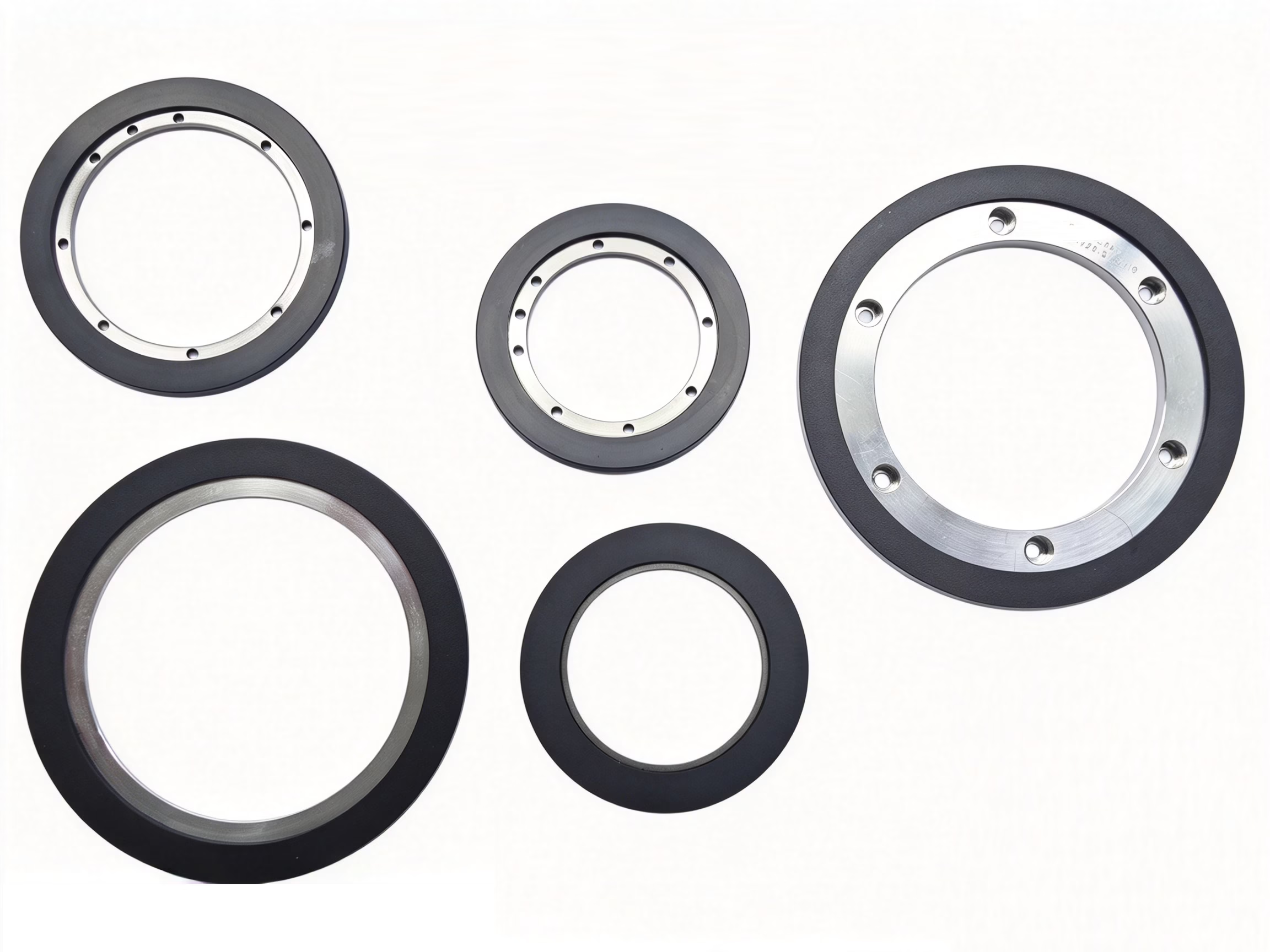
Standard magnetic rings and encoder disks
Compare axial and radial targets, dimensions and Master / Nonius pole-pair combinations. A catalog part may provide a starting point before a custom carrier or mechanical interface is needed.
Explore standard OTV Sensing magnetic rings and encoder disks →Send us the IC choice and the space the ring has to fit
Share the exact chip and package, Master / Nonius pole-pair count, required bore, available OD and thickness, nominal gap, carrier and mounting arrangement. Include temperature, speed, nearby magnetic sources, accuracy target and expected sample or production quantities.
OTV Sensing can review the target geometry, magnetic material, magnetization pattern and mechanical integration with you. If a standard magnetic ring does not fit, contact us to discuss a custom solution.