The NSM3502 Evaluation Board (EVB) from OTV Sensing is a professional evaluation kit built on the NSM3502, NOVOSENSE’s next-generation integrated high-precision off-axis angle and position sensor chip based on Hall array technology.
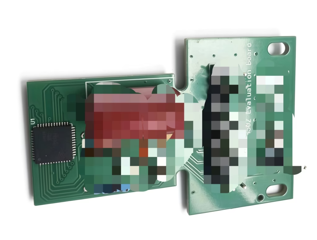
The board integrates power management, signal decoupling and filtering, push-button reset and status indicator circuits, and brings out all core signal interfaces, enabling engineers to rapidly evaluate and develop for motor control, robot joints and industrial automation applications.
Core Features
- Off-axis detection: dual-track vernier Hall array architecture for off-axis and hollow-shaft mechanical installations
- Pole pitch: 2 mm main track; vernier-track pole pitch auto-matched by pole-pair count (1.3 / 1.66 / 1.83 mm)
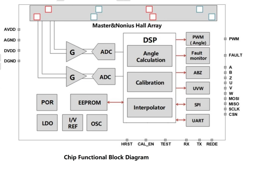
- High resolution: built-in 22-bit angle-solver DSP, up to 4,194,304 absolute positions per revolution
- Multi-interface output: incremental ABZ (up to 65,536 PPR), motor commutation UVW (1–64 pole pairs), PWM, 4-wire SPI and UART
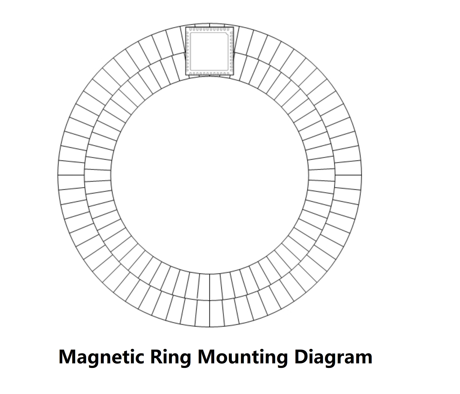
- Magnet ring compatibility: matched to 16-, 32- and 64-pole-pair dual-track magnet rings
- Advanced self-calibration: simple client self-calibration plus constant-speed self-calibration, achieving INL within ±0.1°
- External field immunity: differential Hall sensing actively suppresses uniform external stray magnetic fields
- Comprehensive diagnostics: field out-of-range, overspeed, undervoltage, overtemperature and EEPROM CRC alarms
- Automotive reliability: AEC-Q100 Grade 1 (−40 °C to 125 °C), RoHS & REACH, MSL3
- Programmable storage: built-in 3.3 V–5 V programmable EEPROM for power-off retention of configuration
Technical Specifications
- Supply voltage: 3.0 – 5.5 V
- Resolution: 22-bit (4,194,304 positions per revolution)
- Accuracy: ±0.5° factory, ±0.3° simple calibration, ±0.1° constant-speed calibration
- Max speed: 24,000 RPM (16 pole pairs) / 12,000 RPM (32) / 6,000 RPM (64)
- Power-up time: approx. 50 ms
- Package: QFN48 (7 mm × 7 mm, wettable flanks)
Typical Applications
- Robot joints (hollow-shaft angle feedback in collaborative and humanoid robots)
- Absolute encoder systems for hollow-shaft motors and servo motors
- LiDAR rotary-stage angle monitoring
- High-precision linear displacement and magnetic scale measurement systems
Chip Pin Configuration
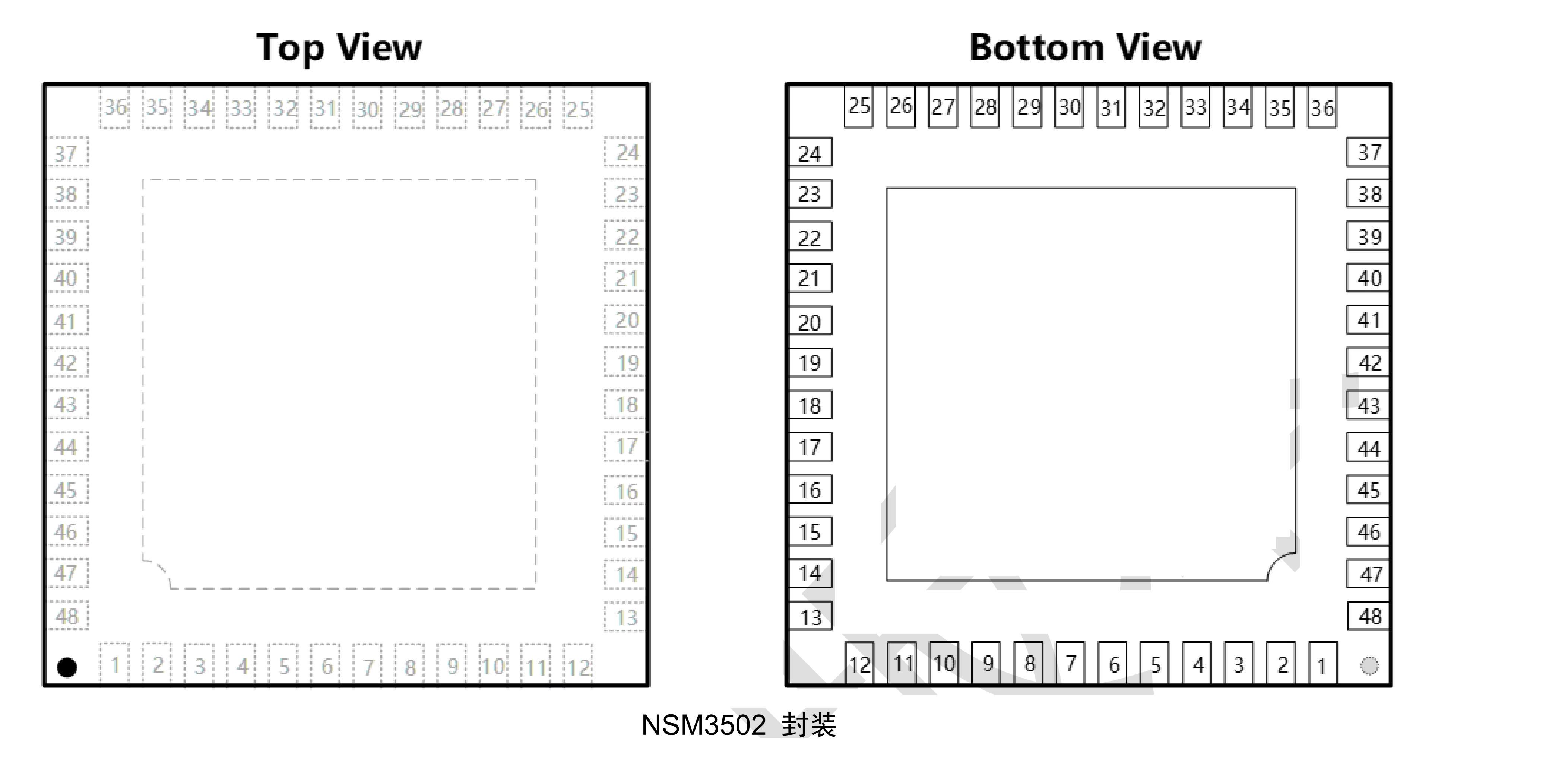
The NSM3502 is available in a QFN48 (7 mm × 7 mm, wettable flanks) package with 48 functional pins and one bottom thermal/ground exposed pad (EPAD 49). The table below lists the name, type and OTV Sensing evaluation-board connection of every pin.
| Pin | Symbol | Type | Function & Board Connection |
|---|---|---|---|
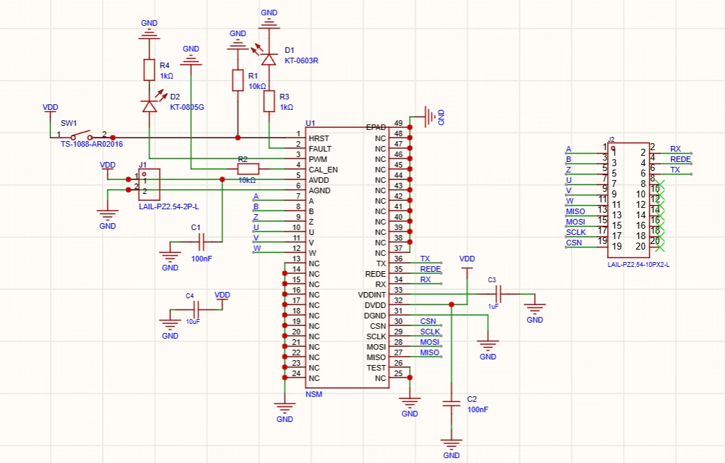
| 1 | HRST | Digital Input | Hardware reset; high >10 ms resets the chip, connected to button SW1 with a 10 kΩ pull-down |
| 2 | FAULT | Digital Output | Diagnostic alarm output, push-pull, active-high by default |
| 3 | PWM | Digital Output | PWM angle output, 12-bit resolution; connected to LED D1 on the board |
| 4 | CAL_EN | Digital Input | Client self-calibration enable; high triggers the self-calibration flow |
| 5 | AVDD | Power | Analog supply input (3.0–5.5 V); 100 nF decoupling capacitor on board |
| 6 | AGND | Power | Analog ground; single-point connected to DGND on board |
| 7 | A | Digital Output | Incremental quadrature A output (push-pull drive) |
| 8 | B | Digital Output | Incremental quadrature B output (push-pull drive) |
| 9 | Z | Digital Output | Incremental index Z output, programmable width (1–128 LSB) |
| 10 | U | Digital Output | UVW commutation U-phase output |
| 11 | V | Digital Output | UVW commutation V-phase output |
| 12 | W | Digital Output | UVW commutation W-phase output |
| 13~25 | NC | No Connect | Internally unconnected; tied to the PCB ground plane for shielding |
| 26 | TEST | Digital Input | Factory test pin; tied directly to ground on the board |
| 27 | MISO | Digital Output | SPI slave output; high-impedance (Hi-Z) when deselected |
| 28 | MOSI | Digital Input | SPI slave input; sampled on the SCLK rising edge |
| 29 | SCLK | Digital Input | SPI clock input; up to 16.6 MHz |
| 30 | CSN | Digital Input | SPI chip-select input, active low, with angle-latch function |
| 31 | DGND | Power | Digital ground; connected to the main ground plane |
| 32 | DVDD | Power | Digital supply input (3.0–5.5 V); 100 nF decoupling capacitor on board |
| 33 | VDDINT | Power Output | Internal LDO output (1.8 V); 1.8 nF internal, 1 µF external decoupling |
| 34 | RX | Digital Input | UART receive pin |
| 35 | REDE | Digital Output | UART transceiver direction-enable pin |
| 36 | TX | Digital Output | UART transmit pin |
| 37~48 | NC | No Connect | Internally unconnected; tied to the PCB ground plane for shielding |
| 49 | EPAD | Thermal Pad | Bottom exposed pad; connected to the ground plane for thermal and shielding |
Package Diagram
Magnetic Ring Mounting
Evaluation Board Hardware
The evaluation board is built around the NSM3502 (QFN48), with supply decoupling circuitry, SW1 hardware reset button, D1 calibration LED and D2 power LED. Power is supplied through J1 (2-pin, 2.54 mm terminal); all angle and communication signals are brought out through J2 (2×10, 20-pin, 2.54 mm dual-row header), covering ABZ, UVW, SPI and UART interfaces for easy connection to motor drives, robot controllers or PLCs.
Core Components & Technical Support
OTV Sensing provides one-stop technical support for core components including the chip, magnet ring and evaluation board. In addition to the NSM3502 evaluation board, we supply the NOVOSENSE NSM3502 chip and matched 16 / 32 / 64 pole-pair dual-track magnet rings (magnetic scales), together with magnet-ring selection, magnetization parameter matching, self-calibration algorithm and production ramp-up support.
For evaluation board loans or selection support, please contact us.