What Is an Inductive Linear Encoder?
An inductive linear encoder is a non-contact absolute position sensor based on electromagnetic induction and eddy current physics. It detects the position of a moving metallic target above a stationary coil assembly, outputting precise linear displacement without optical discs, glass scales, or permanent magnets.
1.1 The Physics: Faraday & Lenz at Work
The operating principle rests on two fundamental laws of electromagnetism:
Faraday’s Law of Induction
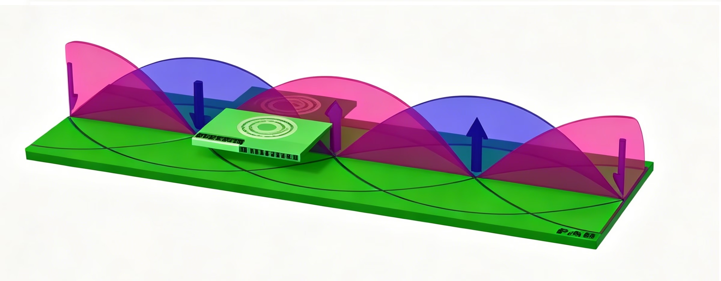
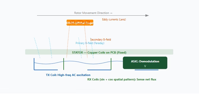
A time-varying magnetic field passing through a conductive loop induces an electromotive force (voltage) in that loop. The stator’s transmit coil carries a high-frequency AC current (typically 1–10 MHz), generating an alternating magnetic field that propagates into the space above the PCB.
Lenz’s Law & Eddy Currents
When the alternating magnetic field encounters a conductive target (rotor), it induces circulating eddy currents within that metal. Per Lenz’s Law, these eddy currents generate their own secondary magnetic field that opposes the original field — altering the net flux sensed by the receive coils below.
1.2 Core Structure: Stator + Rotor
The encoder consists of two parts, following the same architecture as OTV’s proven rotary inductive encoders:
Stator (Fixed Coil Assembly)
A printed circuit board containing three precision-designed coil sets: one transmit (TX) coil and two receive (RX) coil groups arranged in a spatially offset pattern. The TX coil carries a high-frequency AC excitation current (1–10 MHz). The RX coils are geometrically arranged so that the TX-induced magnetic flux couples into them, producing secondary voltages whose amplitude ratio depends on the rotor’s position above the coils. An onboard ASIC demodulates and processes these signals into absolute position output.
Rotor (Moving Metallic Target)
Any electrically conductive material — printed copper patterns on PCB, solid aluminum, steel, or stamped metal — that moves linearly above the stator. As the rotor passes over the coil array, its eddy currents modify the magnetic coupling between TX and RX coils in a position-dependent way. The RX coil voltages encode the rotor’s absolute position. No magnets, no power, no wires on the rotor — completely passive and maintenance-free.
1.3 How Coil Geometry Encodes Position
The receive coils are wound with a spatially periodic geometry — typically a sine/cosine pattern where the winding density varies sinusoidally along the measurement axis. This creates two RX channels with a 90° electrical phase shift (quadrature):
Vsin(x) = A · sin(2πx/P) Vcos(x) = A · cos(2πx/P)
x = rotor position P = electrical pitch (one full sine/cos cycle) A = signal amplitude
The ASIC simultaneously samples both channels, performs arctangent interpolation θ = arctan(Vsin/Vcos), and outputs absolute position. Sub-micron resolution is achieved because the interpolation resolves thousands of counts within each electrical pitch — a pitch of 3 mm can yield 1 µm resolution (3000× interpolation).
Non-contact gap: 0.3–1.0 mm | Rotor materials: copper PCB, aluminum, steel, stamped metal | Absolute position at power-on
▲ TX coil (blue) → alternating B-field (Faraday) → eddy currents in rotor (orange, Lenz) → secondary B-field modulates RX coil voltage → ASIC extracts position
Why Inductive for Linear Measurement?
| Feature | Inductive (OTV-IL) | Optical Linear | Magnetic Linear |
|---|---|---|---|
| Dust / Oil Immunity | ✓ Immune | ✗ Sensitive | ✓ Good |
| Magnetic Field Tolerance | ✓ Immune | ✓ Immune | ✗ Sensitive |
| Rotor / Target Cost | Low (any metal or PCB) | Very high (precision glass scale) | Medium (magnetic tape) |
| Accuracy | ±5 µm | ±1 µm | ±20 µm |
| Absolute at Power-On | ✓ Yes | ✗ Usually incremental | ✓ Yes |
| Max Length | Up to 10 m (scalable) | Up to 30 m | Up to 100 m |
| Operating Temperature | -40°C to +125°C | 0°C to +55°C | -20°C to +85°C |
Product Features
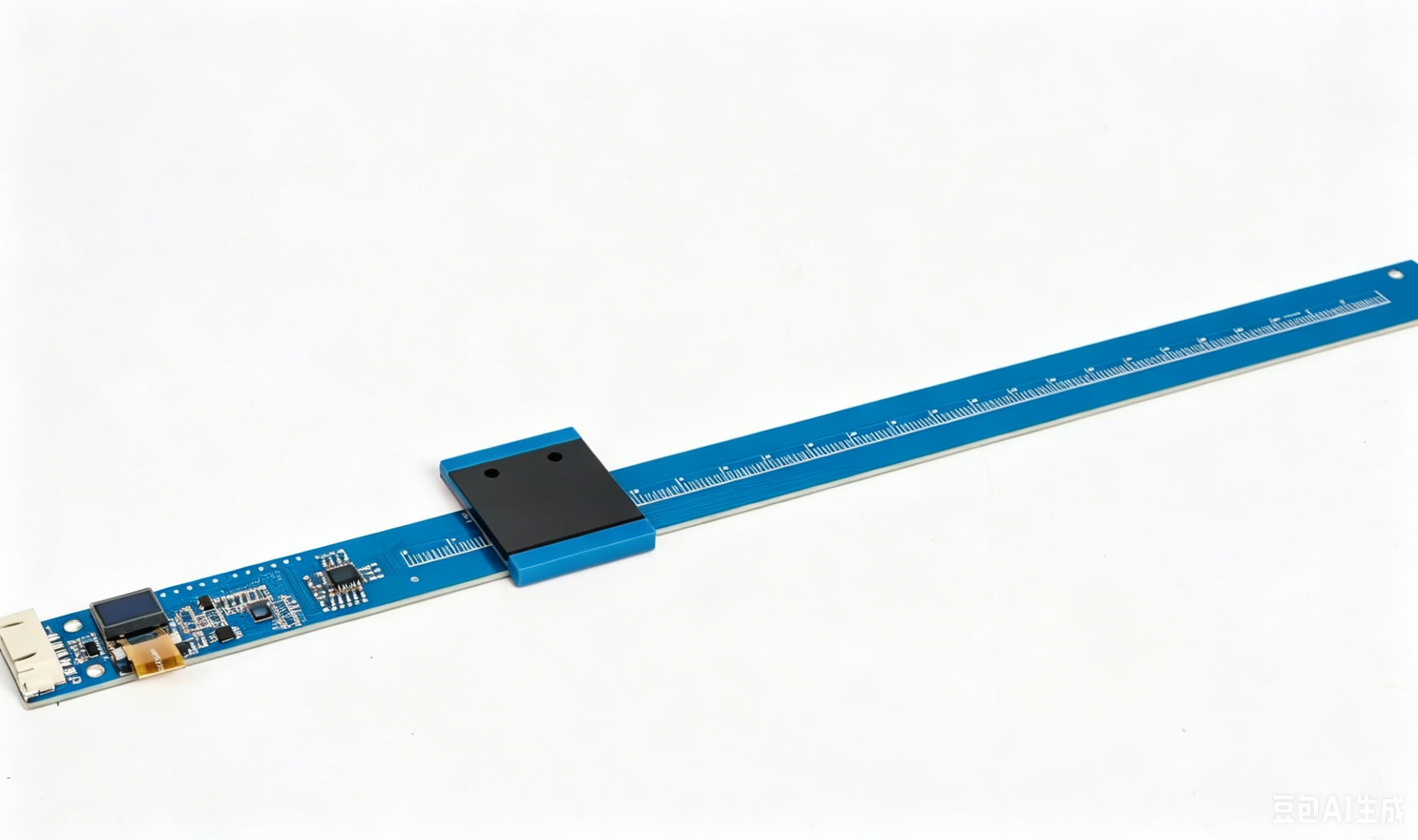
Embedded & Ultra-Thin
Ultra-thin profile — overall thickness only 4 mm. PCB-integrated scale grating (PCB一体栅). Designed for space-constrained embedded motion systems where conventional linear encoders simply won’t fit.
Non-Contact, Zero Wear
Non-contact electromagnetic measurement — no wear, no backlash. Stator and rotor never physically touch. Maintenance-free over the entire service life.
Water & Oil Resistant
Excellent resistance to water, oil mist, and coolant spray. No optical components to fog or contaminate. Reliable operation in harsh industrial environments.
Highly Extensible Form Factor
Rich product morphology extensibility — the stator/rotor architecture adapts to diverse mechanical configurations: linear, curved, segmented, or rotary. Custom coil geometries and rotor shapes available for OEM integration.
OTV-IL Technical Parameters
OTV-IL Series — Ultra-Thin Inductive Linear Encoder
| Item | Parameter | Item | Parameter |
|---|---|---|---|
| Measuring Range | 20 – 300 mm | Resolution | 0.005 – 0.1 mm |
| Air Gap | 0.4 ±0.2 mm | Positioning Accuracy | ±0.1 mm / 300 mm |
| Max Travel Speed | 120 m/min | Power Supply | 5 V DC, 50 mA |
| Scale Mounting | Screw fastening + double-sided adhesive | Signal Output | TTL / RS-485 / SSi / BiSS-C |
Key Technical Advantages
Absolute Position at Power-On
No homing routine. No backup battery. No reference mark search. The encoder knows its exact position the instant power is applied. Simplifies machine startup and recovery from power loss.
Multi-Protocol Output
TTL, RS-485, SSi, and BiSS-C all supported from the same encoder platform. Compatible with PLCs, motion controllers, and embedded MCUs across industrial automation ecosystems.
Harsh Environment Ready
Operates in dust, oil mist, coolant spray, condensation, and vibration. No optical contamination issues. Excellent water and oil resistance. Reliable in demanding industrial conditions.
Flexible Form Factors
The stator/rotor architecture adapts to linear, curved, segmented, or rotary configurations. Custom coil geometries and rotor shapes available for deep OEM integration across diverse applications.
Target Applications
CNC Machine Tools
Axis feedback, tool position, coolant-proof
Pick & Place / SMT
High-speed positioning, sub-micron accuracy
Medical / Lab Automation
Pipetting robots, liquid handling, sterile
Semiconductor Fab
Wafer stages, vacuum-rated, particle-free
Aerospace Actuators
Flight control surfaces, landing gear
Linear Motors
Direct commutation feedback, high dynamics
Custom Linear Encoder Solutions
Every linear motion application has unique constraints — length, profile, environmental exposure, controller compatibility. OTV provides fully customized inductive linear encoder solutions:
Stator (Coil PCB) Customization
Custom coil geometry for pitch, length, and resolution · FR4 or ceramic substrate · Conformal coating for IP67 · Integrated temperature sensor · Connector type and cable exit direction · Multiple readheads for redundancy or extended range
Rotor (Moving Target) Customization
Copper patterns on PCB · Solid aluminum, steel, or stamped metal · Custom pitch and track width · Bolt-down or adhesive mounting · Segmented for long travels · Invar option for near-zero CTE
Protocol & Interface
SSi, BiSS-C, RS-485 (half-duplex) · ABZ incremental quadrature (differential or single-ended) · SPI for embedded MCU integration · Custom baud rates and update rates · CANopen / EtherCAT on request
Calibration & Support
Pre-calibrated at factory with certified reference · FFT-based harmonic compensation stored onboard · PC calibration utility provided · Integration support from our engineering team · NRE competitive; 4-6 week prototype lead time
We also offer linear magnetic encoder solution
Ordering Code Format
OTV-IL-{Length}-{Pitch}-{Resolution}-{Protocol}-{Protection}
Example: OTV-IL-S-200-3-1-BIS-IP67 = S-type, 200mm length, 3mm pitch, 1µm resolution, BiSS-C, IP67 protection
Need a Linear Position Sensing Solution?
Whether you need a standard configuration or a fully customized linear encoder — OTV delivers inductive sensing precision for your motion control application.
Tell us your length, accuracy target, speed, and environmental requirements. We’ll respond with a proposal within 24 hours.
Contact OTV Engineering Team →
thomas@otvsensing.com | Typical response: within 24 hours
OTV Precision Sensing | www.otvsensing.com |