
Magnetic Encoder ICs
Chip selection and precision magnetic targets for rotary position feedback.
OTV Sensing supplies magnetic encoder chips from iC-Haus, TDK, AMS OSRAM, Melexis, NOVOSENSE and CONNTEK. Start with your sensing layout, controller and mechanical envelope. We can support the IC enquiry and the matching magnetic target in the same project.
Choose the sensing layout before the part number
A clear shaft end and a hollow robot joint create different magnetic design problems. The IC must sense the field produced by the target at its actual mounting position.
On-axis magnetic angle sensors
A two-pole magnet rotates above a sensor near the shaft axis. Start here when the shaft end is accessible and a compact magnet fits the assembly.
Example shortlist: AS5047P, AS5048A, AS5600, KTM5200; TAD2141/TAD4140 with the specified rotating field.
Check magnet centering, tilt, field strength and the influence of nearby steel.
Off-axis magnetic encoder ICs
The readhead sits away from the shaft center. Dual-track Master/Nonius sensing is one way to recover absolute position from a multipole ring while keeping the bore open.
Example shortlist: iC-MU family and NSM3502. Review KTM5900 for its device-specific off-axis target arrangement.
Match track geometry, number of pole pairs, scanning radius and installation gap.
Through-shaft and analog feedback
A Triaxis arrangement or an analog sine/cosine front end can fit a different magnetic path. The receiving electronics and field-axis configuration become part of the selection.
Example shortlist: MLX90363 for SPI readout; MLX90380 for analog sine/cosine.
A through-shaft arrangement does not automatically use a dual-track Nonius ring.
Magnetic encoder chip selection by manufacturer and layout
Use the shortlist to identify a sensing architecture and interface. Then compare the exact package, operating conditions and target requirements in the current manufacturer documentation.
13 model entries
| Manufacturer / IC | Layout & magnetic target | Readout & role | Check before choosing |
|---|---|---|---|
| iC-HausiC-MU / iC-MU128Hall array · Master/Nonius | Off-axis dual-track ring; linear-scale configurations | SPI, BiSS/SSI; ABZ and UVW options1.28 mm master pole width | Choose the number of pole pairs, scan diameter and interface configuration together. |
| iC-HausiC-MU150Hall array · Master/Nonius | Off-axis dual-track ring; linear-scale configurations | SPI, BiSS/SSI; ABZ and UVW options1.50 mm master pole width | A different pole width changes the target geometry. Review the mounting radius and ring drawing. |
| iC-HausiC-MU200Hall array · Master/Nonius | Off-axis dual-track ring; linear-scale configurations | SPI, BiSS/SSI; ABZ and UVW options2.00 mm master pole width | Check the selected package, pole pairs, field at the die and calibration requirements. |
| TDKTAD2141TMR with digital processing | 360° angle sensing with a rotating magnetic field | SPI, PWM, ENC/ABZ and UVW modesDigital angle and motor feedback | Define the field vector, compensation method and output mode before fixing the magnet layout. |
| TDKTAD4140Redundant TMR sensing channels | 360° angle sensing with a rotating magnetic field | SPI, PWM, ENC/ABZ and UVW modesDual-channel sensing architecture | Review independent supplies, diagnostic coverage and the safety requirements of the complete system. |
| AMS OSRAMAS5047PMagnetic angle sensor | Shaft-end, two-pole magnet | 14-bit SPI angle; ABI, UVW and PWMMotor-position and commutation feedback | Compare latency, dynamic error, field strength and separate output resolutions. |
| AMS OSRAMAS5048AMagnetic angle sensor | Shaft-end, two-pole magnet | 14-bit SPI angle; 12-bit PWMAbsolute single-turn angle readout | AS5048A uses SPI; an I²C requirement calls for a different variant or interface choice. |
| AMS OSRAMAS5600Magnetic angle sensor | Shaft-end, two-pole magnet | 12-bit angle; I²C, analog/PWMCompact angle and knob sensing | Check bandwidth, noise and the programmed range against the application, rather than resolution alone. |
| MelexisMLX90363Triaxis Hall sensing | Rotary, through-shaft or linear magnetic arrangements | SPIFlexible field-axis measurement | Define the measured field components and magnet trajectory. This is a different architecture from a dual-track Nonius ring. |
| MelexisMLX90380Triaxis magnetic resolver | End-of-shaft or through-shaft arrangements | Analog sine/cosineFast analog position-feedback front end | Budget for the receiving ADC, angle calculation and calibration. No serial absolute-angle output is implied. |
| NOVOSENSENSM3502 · NSM350x seriesDifferential Hall · Nonius | Off-axis, dual-track magnetic ring | SPI, UART, PWM; ABZ and UVWHollow-shaft absolute position designs | Review the released variant, pole geometry and self-calibration procedure. NSM3500/NSM3501 variants can be discussed for the required design. |
| CONNTEKKTM5900TMR angle encoder | On-axis or off-axis target arrangements | SPI, PWM; ABZ and UVWUp to 24-bit reported angle resolution | Verify the selected target and off-axis decoding scheme. A reported angle bit count does not establish whole-revolution absolute accuracy. |
| CONNTEKKTM5200Magnetic angle encoder | On-axis magnetic angle sensing | 21-bit absolute angle over SPI; PWMSelf-calibrating angle feedback | Evaluate magnet eccentricity, calibration travel and residual system error on the actual assembly. |
No matching entries. Reset the filters or contact OTV Sensing with the required part number.
NSM350x series enquiries can include NSM3500, NSM3501 and NSM3502. Confirm the released device, sample availability and full ordering code for your project. Each family needs its own validated target; similar dimensions do not establish interchangeability.
Eight checks that matter more than the headline bit count
Accuracy, resolution and repeatability
Set a permissible angular error over the actual speed and temperature range. A 14-bit output has a 0.022° code step; that number is not an accuracy specification. Compare INL, noise, repeatability and calibration conditions separately.
Latency and control-loop timing
Check sensing bandwidth, filtering, conversion delay and the age of the returned angle. As a first-order check, delay error in degrees = 6 × speed in rpm × delay in seconds. At 3,000 rpm, 10 µs corresponds to 0.18° before any prediction or compensation.
Magnetic target and field budget
Specify the field components, operating amplitude, magnetization direction, scan diameter, number of pole pairs and track spacing. Evaluate the field at the sensing die across gap, temperature and production tolerances.
Controller interface and output mode
Match SPI mode and frame format, BiSS/SSI timing, CRC or status bits, logic levels and startup behavior. ABZ is incremental feedback; its presence does not make an interface absolute. UVW supports motor commutation.
Mechanical installation
Define shaft-to-ring concentricity, axial runout, PCB position, chip orientation and package clearance. A correct nominal air gap is only one part of the tolerance stack. Nearby steel can reshape the magnetic field.
Supply, temperature and diagnostics
Check supply rails, I/O voltage, current consumption, junction versus ambient temperature, EMC exposure and fault reporting. Confirm qualification and safety documentation for the exact order code and package.
Calibration and production testing
Plan how the assembly rotates during calibration, how settings are retained and how each unit is checked. Verify startup at several positions, both directions of motion, temperature corners and a full revolution after power cycling.
Package, lifecycle and purchasing
Confirm the complete manufacturer part number, package, temperature grade, packing format, sample quantity and production forecast. Evaluate lifecycle and change notifications together with price, lead time and the validation cost of an alternative.
Magnetic encoder IC + Precision magnetic ring
OTV Sensing can provide the chip and a magnetic target designed around the selected sensing architecture. We review the IC requirements alongside the shaft, housing, PCB and operating conditions so the magnetic and mechanical decisions stay aligned.
Agree the sensing geometry
Choose the exact IC, field orientation, number of pole pairs and track layout. For a hollow-shaft design, establish the bore, scanning radius and available mounting envelope before releasing the target drawing.
Match the precision target
Review ring or disc dimensions, carrier, magnetic material, axial or radial magnetization and mounting features. The target is matched to the chosen IC; a universal ring is not assumed.
Validate the assembled system
Check field and signal quality, then quantify angular error, calibration residuals, startup behavior and temperature effects in the real mounting arrangement.
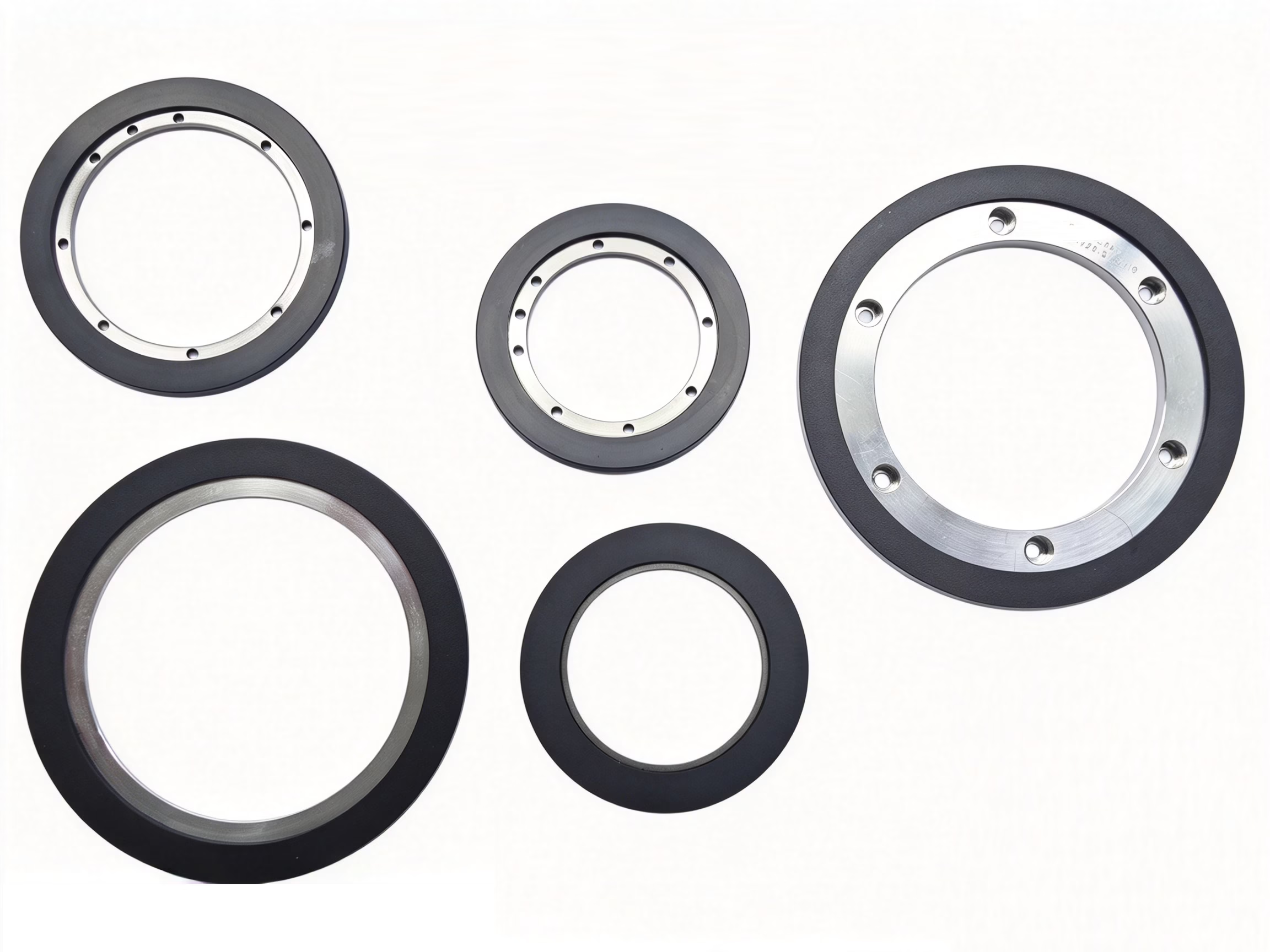
Standard magnetic rings & discs
Compare axial and radial structures, dimensions and target options.
Browse magnetic encoder targets →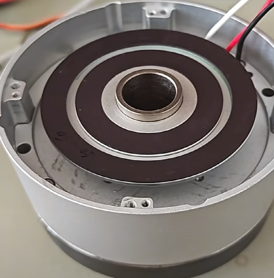
iC-MU ring design
Work through scan diameters, pole width, number of pole pairs and the mounting radius.
Open the engineering guide →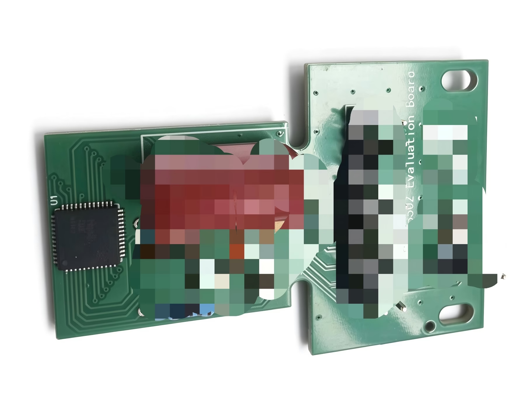
NSM3502 evaluation board
Explore a development path for the NSM3502 and a matching magnetic target.
Review the evaluation board →Need a complete encoder instead of discrete components? Compare OME and OMEC off-axis magnetic encoders. Already have electronics? Discuss a custom magnetic ring.
Magnetic encoder IC selection FAQ
Which magnetic encoder IC should I use for a hollow-shaft motor?
Start with the available bore, ring diameter, PCB location and operating gap. iC-MU family and NSM3502 are candidates for dual-track off-axis sensing. Other through-shaft arrangements use different field geometries; select the target and electronics as a system.
Can a magnetic ring be shared between different encoder chips?
Only after the magnetic and mechanical requirements have been compared and the assembly validated. Pole width, number of pole pairs, track spacing, field direction and signal processing can differ even when the ring dimensions look similar.
Does a 24-bit chip provide 24-bit absolute accuracy?
No. Reported resolution is a digital code step. Noise, nonlinearity, target error, mounting and temperature determine the usable system performance. With a multipole target, also confirm how the system identifies position across the entire mechanical revolution.
Do all magnetic angle sensors work with a multipole Nonius ring?
No. Shaft-end angle sensors commonly use a two-pole magnet. A dual-track Nonius ring requires a sensor and decoding scheme designed for that track geometry. Through-shaft Triaxis sensing is another arrangement and should not be treated as interchangeable.
Can OTV Sensing supply encoder chips without a magnetic ring?
Yes. Send the full manufacturer part number, package, quantity, delivery destination and required date for an IC quotation. A matching ring, custom target and engineering review can be included in the same enquiry.
What information is needed for an IC and magnetic ring proposal?
Share the preferred chip or sensing layout, required bore and envelope, speed, accuracy target, temperature range, controller interface and sample or production quantity. A shaft and PCB drawing helps identify target and installation constraints early.
iC-MU150 / Encoder IC packaging and order quantities
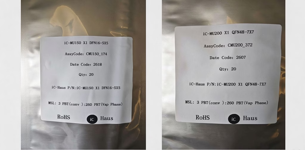
Order the quantity your project needs
OTV Sensing supplies chips in the quantities requested by the customer. When a partial pack is required, we split and repack the requested quantity for supply.
We will confirm availability, packing format and the quoted quantity before order confirmation.
Bring the IC and magnetic ring into the same enquiry
Tell us what the encoder needs to measure and where it needs to fit. OTV Sensing can quote magnetic encoder chips, review a matching precision ring and help define the next evaluation step.
For chip-only orders, send your BOM line and required quantity. For a matched solution, add the mechanical drawing and sensing requirements. We will confirm the exact order code, availability, lead time and scope of supply in the quotation.
Device documentation and further reading
Use the current manufacturer datasheet for electrical limits, interface details, qualification and ordering codes. These links support initial selection; the application must be validated for the selected chip and target.