
Hollow Inductive Encoders for Absolute Rotary Position Feedback
Compare OTV-INED encoder configurations by stator bore, ring dimensions, resolution, stated accuracy and interface. The range spans stator inner diameters from 5 mm to 100.5 mm for integration into robotic joints, rotary mechanisms and industrial equipment.
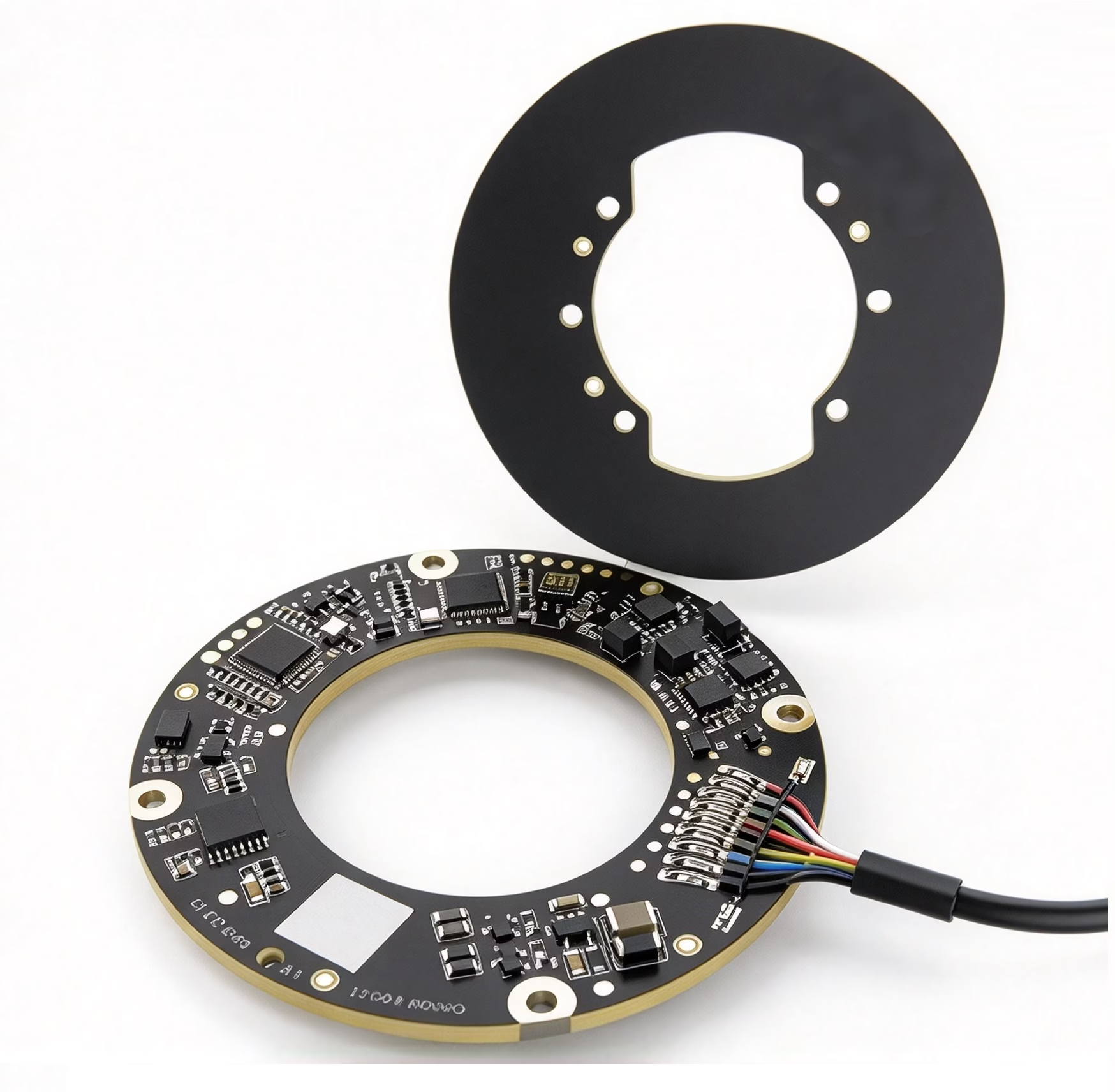
Contactless sensing built around the rotary assembly
An inductive encoder measures angular position using electromagnetic induction. The stationary stator generates an alternating field; as the rotor code ring turns, it modulates that field. The encoder electronics process the changing signal to determine angular position without a contacting readhead.
Stator and rotor code ring
The stator remains fixed while the rotor ring rotates with the measured axis. Select both rings as a matched mechanical and electrical configuration.
Designed for demanding installations
The product manual highlights resistance to oil, iron powder, external magnetic fields and mounting eccentricity. Confirm allowable conditions and installation limits for the selected model.
Hollow-bore rotary feedback
The ring format leaves a central opening for shafts, cables or adjacent mechanical components. Check stator and rotor dimensions independently against your available envelope.
For compact rotary axes and larger hollow shafts
We offer inductive encoders for robotics, industrial automation, industrial equipment, machine tools, automotive electronics and consumer electronics. The listed INED configurations cover small-bore assemblies through larger rotary platforms.
Match the encoder to the actual mechanical stack: mounting faces, stator and rotor diameters, ring thickness, air gap, axis runout and cable routing. The correct installation gap is model-specific; use the drawing for the selected configuration.
A five-step model selection workflow
- 1. Measure the mechanical envelope. Check stator and rotor inner and outer diameters, available axial space and shaft clearance.
- 2. Define position performance. Set the required accuracy or repeatability and resolution separately; bit count is not an accuracy value.
- 3. Match the output. The listed configurations show RS485 or SPI. Confirm the exact interface, connector and cable exit for the selected model.
- 4. Confirm turns and installation. Select single-turn or multi-turn feedback, then verify the model drawing, mounting gap and allowable runout.
- 5. Check the operating environment. Confirm temperature, EMC, contamination exposure and application-specific limits against the selected model data.
Where hollow inductive encoders fit
Hollow inductive encoders provide non-contact rotary position feedback while leaving a center opening for a shaft, cable or adjacent mechanism. Use these application examples to identify the parameters to check, then confirm the final fit with the selected model drawing.
Robot joints and hollow-shaft actuators
Compare the available bore and outer diameter with the joint envelope. Confirm required resolution, single-turn or multi-turn feedback, interface and cable routing.
Explore OTV-INE and OTV-INEC encoder optionsRotary tables and precision stages
Check stator and rotor dimensions, mounting gap, runout, target accuracy, resolution and controller interface before selecting a ring size.
See OTV rotary table encoder solutionsMachine tools and CNC axes
Review the mounting envelope and verify the required tolerance to oil, iron particles, external magnetic fields, temperature and EMC for the exact model.
Industrial automation and equipment
Match the encoder to the shaft size, available axial space, control interface, output arrangement and motion profile of the rotary axis.
Key specifications across the OTV-INED range
Use these range-level values to narrow the model list. Individual dimensions, resolution, accuracy and interface are shown in the comparison table below.
±0.00139–±0.00556°
200 mA max.
Ranges summarize the models listed on this page. Dimensions are shown as inner diameter × outer diameter; check the selected model row for its exact values.
OTV-INED hollow inductive encoder models
The product identifiers below are assigned from each model stator-board inner diameter. The three-digit size is the nearest whole millimeter; a series suffix distinguishes models that share a nominal bore. Exact dimensions remain in the table.
| OTV product name | Product thumbnail | Stator Dia. ID x OD (mm) | Rotor Dia. ID x OD (mm) | Resolution | Accuracy (arc-sec / deg) | Interface |
|---|---|---|---|---|---|---|
| OTV-INED-005 | 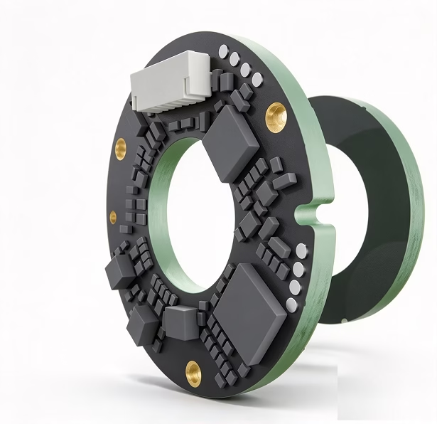 | 5 x 18 | 5 x 12 | 17 bit | +/-20 arc-sec +/-0.00556 deg | RS485 / SPI |
| OTV-INED-009 | 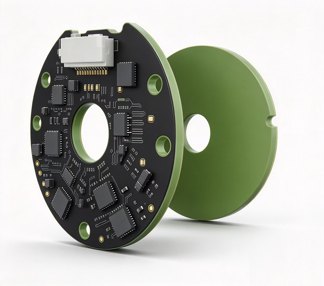 | 9 x 35 | 6 x 25 | 17 bit | +/-10 arc-sec +/-0.00278 deg | RS485 |
| OTV-INED-010-B | | 10 x 23 | 10 x 17 | 17 bit | +/-20 arc-sec +/-0.00556 deg | RS485 / SPI |
| OTV-INED-010-S | Image to be added | 10 x 23 | 10 x 17 | 11 bit | +/-10 arc-sec +/-0.00278 deg | RS485 |
| OTV-INED-012-G | Image to be added | 12 x 35 | 11 x 28.2 | 17 bit | +/-20 arc-sec +/-0.00556 deg | RS485 |
| OTV-INED-012-M | Image to be added | 12 x 35 | 12 x 25.7 | 17 bit | +/-10 arc-sec +/-0.00278 deg | RS485 |
| OTV-INED-015 | Image to be added | 15 x 28 | 15 x 22 | 17 bit | +/-10 arc-sec +/-0.00278 deg | RS485 / SPI |
| OTV-INED-016 | Image to be added | 16 x 45 | 10 x 45 | 23 bit | +/-10 arc-sec +/-0.00278 deg | RS485 |
| OTV-INED-017 | Image to be added | 17 x 45 | 17 x 34.6 | 17 bit | +/-10 arc-sec +/-0.00278 deg | RS485 |
| OTV-INED-020-B | Image to be added | 20 x 33 | 20 x 27 | 17 bit | +/-10 arc-sec +/-0.00278 deg | RS485 / SPI |
| OTV-INED-020-M | Image to be added | 20 x 55 | 20 x 44.6 | 17 bit | +/-10 arc-sec +/-0.00278 deg | RS485 |
| OTV-INED-025 | Image to be added | 25 x 38 | 25 x 32 | 19 bit | +/-10 arc-sec +/-0.00278 deg | RS485 / SPI |
| OTV-INED-030 | Image to be added | 30 x 43 | 30 x 37 | 19 bit | +/-10 arc-sec +/-0.00278 deg | RS485 / SPI |
| OTV-INED-034-G | Image to be added | 33.5 x 60 | 25 x 50.5 | 19 bit | +/-12 arc-sec +/-0.00333 deg | RS485 |
| OTV-INED-035 | Image to be added | 35 x 48 | 35 x 42 | 19 bit | +/-10 arc-sec +/-0.00278 deg | RS485 / SPI |
| OTV-INED-040 | Image to be added | 40 x 53 | 40 x 47 | 19 bit | +/-10 arc-sec +/-0.00278 deg | RS485 / SPI |
| OTV-INED-045-G | Image to be added | 44.5 x 80 | 35 x 69.9 | 19 bit | +/-12 arc-sec +/-0.00333 deg | RS485 |
| OTV-INED-045-B | Image to be added | 45 x 58 | 45 x 52 | 19 bit | +/-10 arc-sec +/-0.00278 deg | RS485 / SPI |
| OTV-INED-050 | Image to be added | 50 x 63 | 50 x 57 | 19 bit | +/-10 arc-sec +/-0.00278 deg | RS485 / SPI |
| OTV-INED-055 | Image to be added | 55 x 68 | 55 x 62 | 19 bit | +/-10 arc-sec +/-0.00278 deg | RS485 / SPI |
| OTV-INED-058 | Image to be added | 58 x 100 | 48.5 x 88.5 | 23 bit | +/-5 arc-sec +/-0.00139 deg | RS485 |
| OTV-INED-060 | Image to be added | 60 x 73 | 60 x 67 | 19 bit | +/-10 arc-sec +/-0.00278 deg | RS485 / SPI |
| OTV-INED-065 | Image to be added | 65 x 78 | 65 x 72 | 19 bit | +/-10 arc-sec +/-0.00278 deg | RS485 / SPI |
| OTV-INED-066 | Image to be added | 65.5 x 95 | 65.5 x 85 | 17 bit | +/-5 arc-sec +/-0.00139 deg | RS485 |
| OTV-INED-070 | Image to be added | 70 x 83 | 70 x 77 | 19 bit | +/-10 arc-sec +/-0.00278 deg | RS485 / SPI |
| OTV-INED-075 | Image to be added | 75 x 88 | 72 x 82 | 19 bit | +/-10 arc-sec +/-0.00278 deg | RS485 / SPI |
| OTV-INED-080 | Image to be added | 80 x 93 | 80 x 87 | 19 bit | +/-10 arc-sec +/-0.00278 deg | RS485 / SPI |
| OTV-INED-085 | Image to be added | 85 x 98 | 85 x 92 | 19 bit | +/-10 arc-sec +/-0.00278 deg | RS485 / SPI |
| OTV-INED-101 | Image to be added | 100.5 x 140 | 90.5 x 130.5 | 23 bit | +/-5 arc-sec +/-0.00139 deg | RS485 |
Electrical and environmental specifications
Electrical and environmental specifications for the OTV-INED encoder range.
Hollow inductive encoder selection FAQs
What is a hollow inductive encoder used for?
It measures rotary angle without a contacting optical readhead. The open center accommodates a shaft or other components, making the format useful for robot joints, rotary mechanisms and industrial equipment.
How do I choose the right OTV-INED model?
Begin with the stator inner and outer diameters, then check the rotor-ring dimensions and thickness, mounting gap, required resolution, stated accuracy, interface and turn-count behavior. Use the model-specific drawing to verify the mechanical stack.
How is accuracy in arc-seconds shown in degrees?
Divide arc-seconds by 3,600. For example, 10 arc-seconds equals about 0.00278 deg. Resolution in bits is a separate parameter and does not by itself define angular accuracy.
Which bore sizes are covered?
The models listed here span stator inner diameters from 5 mm to 100.5 mm. Several model families share a nominal bore, so compare their exact stator and rotor dimensions and interface before choosing.
Need help matching a bore, interface or encoder configuration?
Send OTV the shaft and mounting dimensions, target accuracy, resolution, interface and operating conditions. The team can help confirm the suitable model and drawing.