
Robot joint feedback · Chip and magnetic target
iC-MUE for Robot Joint Encoders: Features & Matched Magnetic Rings
The iC-MUE magnetic off-axis absolute encoder IC from iC-Haus combines Hall sensing, signal processing and on-chip adjustment in a 7 × 7 mm package. Its dual-track Nonius architecture suits hollow-shaft robot joints, where the magnetic ring surrounds the shaft and the sensor sits beside the reading track.
OTV Sensing supplies iC-MUE chips and custom multipole magnetic rings for matched encoder designs. Share your joint geometry, pole-pair requirement and controller interface to start the selection process.
Discuss an iC-MUE chip and ring project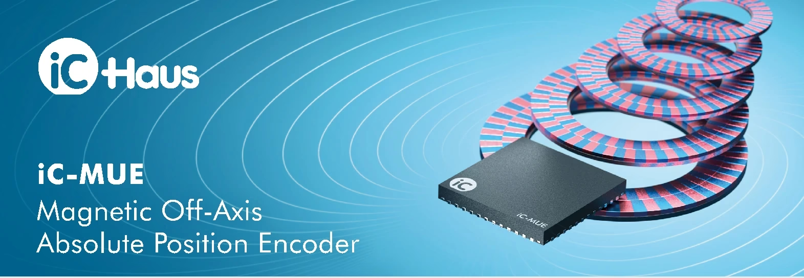
Why iC-MUE Fits Hollow-Shaft Robot Joint Encoders
Robot joint modules must accommodate bearings, a motor, transmission components and often a central passage for cables. An off-axis magnetic encoder places the sensing IC away from the shaft centre, allowing the magnetic target and PCB to fit around that mechanical space.
iC-MUE reads two magnetic tracks to determine absolute position within the configured single-turn range after startup, without a reference search. In a robot joint, that can simplify position acquisition at power-up. The complete controller still needs its normal startup checks and safety sequence.
Commutation and Rotor Position
Serial position data, programmable ABZ signals and UVW commutation outputs provide options for integrating feedback with a motor controller. The UVW generator supports motors with 1–32 pole pairs.
Measure the Output Shaft
A ring on the joint output can measure the position after the transmission. A separate motor-side and output-side measurement architecture can support assessment of transmission behaviour; it requires two appropriately integrated sensing systems.
For the broader product options, see OTV’s off-axis absolute rotary magnetic encoders. For a target-focused engineering reference, use the existing iC-MUE magnetic ring design guide.
How Dual-Track Nonius Sensing Produces Absolute Position
The magnetic target carries a master track and a Nonius track. With a conventional neighbouring-count combination, the tracks have different pole-pair counts, such as N and N−1. Their changing phase relationship identifies the position around one complete revolution, while interpolation resolves position within the magnetic pattern.
iC-MUE supports decimal Nonius combinations and 8–64 pole pairs, allowing the target geometry to be selected within the chip’s supported design rules.
Differential magnetic scanning helps suppress external magnetic interference. Automatic gain control and adjustment routines support signal conditioning. These functions assist integration, but the magnetic field, sensing gap, runout and nearby motor fields still need to be evaluated in the assembled joint.
iC-MUE Key Features and Technical Specifications
The following values come from the supplied iC-Haus MUE factsheet, Rev. 1.0. Maximum values and typical examples refer to their stated configurations; they are not a guarantee that every setting can be combined.
| Parameter | Factsheet value / feature | What to check in a joint design |
|---|---|---|
| Sensing principle | Magnetic Hall off-axis absolute sensing; dual-track Nonius; rotary or linear | Select track geometry and sensor orientation together. |
| Magnetic track selection | 8–64 pole pairs; Hall sensors optimized for 2.00 mm master-track pole width | Define single-pole width at the actual reading diameter. |
| Single-turn resolution | Up to 22 bit; example: 21 bit with a Ø44 mm code disc and 32 pole pairs | Resolution is not assembled-system accuracy. |
| Expanded acquisition | Three-track systems up to 26 bit; multiturn resolution up to 32 bit | Three-track extension uses an additional iC-MUE; multiturn uses an internal revolution counter or external sensor architecture. |
| Noise-free resolution | Typically 12 bit per pole pair, ±3 sigma | Assess noise and usable resolution at the required bandwidth. |
| Absolute accuracy example | Typically <0.04° at 32 pole pairs, calibrated with LUT linearization | Requires the stated calibration; it is not an uncalibrated guarantee for an OTV ring. |
| Rotation speed | Up to 12,000 rpm at 32 pole pairs | Verify the required pole count, signal configuration and mechanical limits. |
| Typical air gap | 0.6 mm +0.3/−0.2 mm | Allow for assembly stack-up and verify the selected target. |
| Main supply | 3.0–5.5 V; typically 65 mA | Budget power and thermal conditions for the complete circuit. |
| I/O supply | 2.25–5.5 V; supports 2.5 V, 3.3 V and 5 V-compatible ports | Match the controller’s electrical levels. |
| Ambient operating temperature | −40 to +125°C | The ring, carrier, PCB and adhesives need their own temperature assessment. |
| Package | QFN48, 7.0 × 7.0 mm, 0.9 mm thick | Review PCB layout, placement and sensing-track alignment. |
The factsheet is preliminary product information. Use the current iC-Haus specification for electrical design release and confirm the intended configuration.
Interfaces for Robot and Servo Controller Integration
- Absolute serial data: BiSS up to 10 MHz or SSI up to 4 MHz, and SPI up to 12 MHz. The factsheet describes CRC protection, an optional sign-of-life counter, and programmable error/warning bits.
- Incremental feedback: a programmable FlexCount® ABZ generator, with 1–65,536 AB cycles and AB frequency up to 18 MHz.
- Motor commutation: UVW outputs for motors with 1–32 pole pairs.
- Analog outputs: differential Sin/Cos outputs, described as “safety-ready” by iC-Haus. This feature alone does not establish a certified functional-safety rating for an encoder or robot joint.
- Configuration and expansion: I²C master/slave access for configuration and diagnostics, plus an Absolute Data Interface for supported external multiturn sensors or a further iC-MUE in an expanded system.
BiSS/SSI and SPI support simultaneous use, subject to port assignment. Select the interfaces and output resolution needed by the actual controller rather than assuming every output function is available on the same pins at once.
On-Chip Adjustment, Eccentricity Compensation and Calibration
The chip supports automatic adjustment triggered by a pin or command. Eccentricity compensation and a lookup table help correct repeatable angular errors in the installed system. For LUT linearization against an external angle reference, a suitable reference measurement is still part of the calibration process.
The factsheet’s typical <0.04° accuracy example applies at 32 pole pairs after calibration and LUT linearization. It should be considered separately from the 21- or 22-bit output-resolution figures. The final error budget also includes ring magnetisation, concentricity, sensor placement, bearing runout, thermal changes and the calibration reference.
OTV Sensing Custom Multipole Magnetic Rings for iC-MUE
A compatible ring needs more than the correct outside diameter. OTV Sensing can customize the mechanical dimensions, carrier and magnetic track layout for an iC-MUE-based encoder, then review the target against the selected chip configuration and assembly geometry.
Axial Reading
The sensor faces magnetic tracks on the ring’s flat surface. Review the bore, ring thickness, reading-track radii, PCB location, axial gap and face runout.
Radial Reading
The sensor reads tracks on a cylindrical target. Review the sensing diameter, radial clearance, track position and concentricity of the complete rotating assembly.
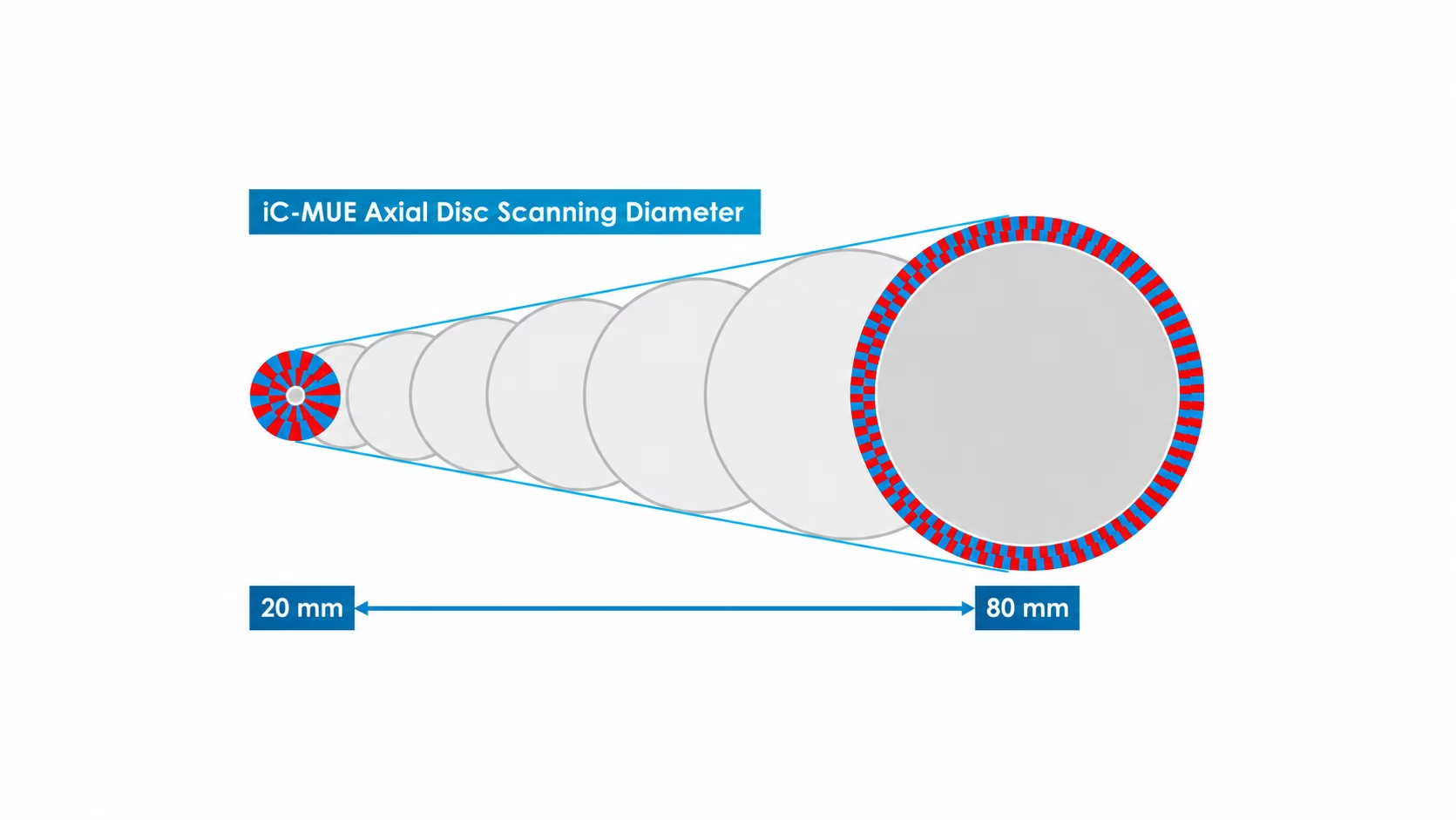
The factsheet gives illustrative axial ring outside diameters of 20–85 mm and radial outside diameters of 15–80 mm, with exact dimensions dependent on the individual magnetic target. These are chip-application design ranges, not a ready-stock catalogue or a promise that every bore, track count and outside diameter can be combined.
Pole-width example: for a circular master track with N pole pairs and a single-pole arc width w, the nominal reading diameter is D = 2Nw/π. At 32 pole pairs and w = 2 mm, D is approximately 40.74 mm. This is the magnetic reading diameter, not the ring’s outside diameter; the factsheet’s Ø44 mm disc example includes the surrounding geometry.
Use our magnetic encoder ring design tool to submit a dual-track custom requirement and select iC-MUE as the intended IC. Browse OTV magnetic encoder rings and discs for the available target architectures.
Source the iC-MUE Chip and Matched Magnetic Target from OTV Sensing
OTV Sensing can supply the iC-MUE chip alongside a custom magnetic ring requirement, helping customers coordinate chip selection, target geometry and the information needed for sample evaluation. Send the chip quantity and target quantity separately; availability, commercial terms and delivery dates are confirmed with the quotation.
For a target already designed for another IC, share the complete drawing and magnetisation data. A shared nominal 2 mm master pole width does not establish full compatibility with iC-MUE. The readout geometry, Nonius combination, field conditions and chip configuration need to be checked together.
- Define the joint: shaft bore, outside diameter, thickness, available PCB space, axial/radial reading direction and operating temperature.
- Define feedback: single-turn or multiturn behaviour, pole-pair counts, resolution, accuracy target, maximum speed and controller interface.
- Review the matched design: magnetic tracks, carrier, mounting, sensing gap, tolerance stack and relevant chip configuration.
- Evaluate the sample: verify signal quality and absolute decoding across the assembly tolerances, then measure accuracy and repeatability before design release.
Planning an iC-MUE Robot Joint Encoder?
Send OTV Sensing your ring drawing or mechanical envelope, reading direction, required pole-pair counts, interface and sample/annual quantities. We can review a custom multipole magnetic ring and provide a quotation for the iC-MUE chips and targets.
Request chip and magnetic ring selectioniC-MUE Robot Joint Encoder FAQ
Does iC-MUE provide 22-bit absolute accuracy?
Up to 22 bit describes single-turn resolution. The factsheet separately lists a typical absolute accuracy below 0.04° at 32 pole pairs after calibration and LUT linearization.
Can the encoder preserve multiturn position without power?
The factsheet lists an internal revolution counter and interfaces for external multiturn solutions. Power-off turn retention depends on the chosen architecture; an internal counter alone should not be treated as a battery-free, power-loss-retentive multiturn system.
Can OTV customize a hollow-shaft ring for iC-MUE?
Yes. Provide the bore, outside diameter, thickness, axial/radial reading direction and required magnetic configuration. OTV will review the dimensions and track design for the intended assembly.
Can I purchase the iC-MUE chip together with the ring?
Yes. OTV Sensing accepts enquiries for chip supply and custom matched magnetic targets. Include quantities for both so the quotation can address each item.
References and Further Reading
Technical parameters: supplied iC-Haus MUE factsheet, Rev. 1.0, pages 1–2; current manufacturer information: iC-Haus iC-MUE product page. Application context: messweb, “iC-MUE für präzises Positionsfeedback in Robotergelenken,” 11 November 2026. This article presents an original English application discussion, with OTV Sensing’s chip and magnetic-target supply offering.