
PCB-level incremental encoder selection
RLC2HD Alternative: OTV PCB Encoders, Magnetic Rings & Scales
Evaluating an alternative to the RLS RLC2HD? OTV Sensing offers ICRM PCB readheads for rotary feedback, IML200-PCB readheads for linear feedback, and custom magnetic rings or scales to suit the application.
Start with the motion, required output increment and controller interface. These OTV options support a new matched encoder design; they are not established pin-for-pin or solder-footprint replacements for RLC2HD.
Request an encoder alternative reviewChoose an OTV Alternative for Rotary or Linear Feedback
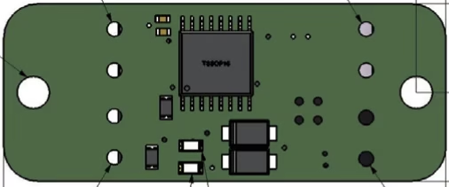
ICRM PCB Rotary Encoder
A compact 30 × 12 mm PCB readhead sits beside a rotating magnetic ring. The shaft passes through the ring, while the readhead fits into the surrounding mechanism.
- 5 V supply and differential A/B/Z options.
- Unique index available with the corresponding magnetic target.
- Operating temperature: −30 to +80°C.
Consider ICRM for hollow-shaft assemblies, motor feedback and embedded rotary mechanisms where the readhead and ring can be selected together.
Explore ICRM and matched incremental rings →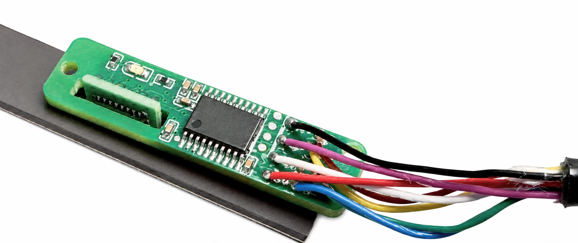
IML200-PCB Linear Readhead
A 30 × 8 × 4.4 mm board-level incremental readhead for machine builders integrating feedback into their own mechanism or enclosure.
- 5 V supply; 1, 2 or 10 μm resolution options.
- Digital TTL/RS422 A/B/Z configurations.
- Up to 5 m/s on the applicable configuration.
- Operating temperature: −20 to +80°C.
Pair the board with a matched magnetic scale and unique-reference configuration. Review cable length, connector and environmental protection as part of the assembly.
Explore IML200-PCB and linear encoder options →What Does the RLS RLC2HD Provide?
The RLC2HD is a miniature PCB-level incremental magnetic readhead for linear scales and rotary rings. The supplied RLS datasheet, RLCD03_09, Issue 09 dated 4 September 2024, specifies an approximately 8 × 2.1 × 12.5 mm package, a 5 V supply and single-ended TTL A/B/Z signals without a line driver.
Its finest listed output increment is approximately 0.244 μm, using the 8192 interpolation setting. This is an incremental interpolation figure, not absolute shaft position and not a statement of system accuracy. For linear use, RLS lists MS05 scale accuracy grades of ±10, ±20 or ±40 μm/m.
RLC2HD’s periodic Z signal repeats every 2 mm of travel along the magnetic pattern. On a ring, that does not automatically produce a unique once-per-revolution index. Maximum speed must be checked for the selected resolution and minimum edge separation using the manufacturer’s configuration guidance.
RLC2HD vs OTV ICRM and IML200-PCB: Specification Comparison
Compare complete sensing systems. A readhead’s resolution, magnetic target and receiving electronics jointly determine whether an alternative meets the application.
| Selection item | RLS RLC2HD | OTV ICRM | OTV IML200-PCB |
|---|---|---|---|
| Motion / architecture | Linear or rotary miniature PCB-level readhead | Open PCB rotary readhead beside a separate magnetic ring | Board-level linear readhead with a matched scale |
| Supply | 5 V ±0.25 V at the readhead | 5 V | 5 V |
| Position output | Single-ended TTL A/B/Z; no line driver | Differential A/B/Z / RS422 options | Digital TTL/RS422 incremental A/B/Z; select the wiring configuration |
| Resolution selection | Finest listed increment ≈0.244 μm; other ordering options include 1, 2 and 10 μm | Select PPR with the ring and readhead configuration | 1 / 2 / 10 μm |
| Reference signal | Periodic bidirectional Z, every 2 mm of magnetic pattern | Unique index with the corresponding target | Unique-reference configuration with a matched scale |
| Operating temperature | −30 to +85°C | −30 to +80°C | −20 to +80°C |
| Mechanical integration | Approx. 8 × 2.1 × 12.5 mm; SMT assembly onto a customer PCB | 30 × 12 mm PCB; two Ø2.2 mm mounting holes | 30 × 8 × 4.4 mm; use the mounting and sensing drawing for the selected assembly |
| Speed selection | Resolution and edge-separation dependent; use the RLS speed calculator | Review ring geometry, PPR and controller count rate | Up to 5 m/s, configuration-dependent |
| Magnetic target | Specified 2 mm pole length; matched MS05 scale or corresponding RLS ring | Matched incremental rotary ring and reference feature | Matched 2 mm magnetic scale and reference feature; verify the pitch definition |
RLC2HD figures are from the supplied Issue 09 datasheet. OTV figures follow the linked product information. The comparison does not establish interchangeability or equal accuracy. Open PCB readheads require protection within the equipment assembly.
Five Checks Before Replacing an RLC2HD Readhead
1. Confirm the required increment and error budget
If the existing design uses the RLC2HD’s approximately 0.244 μm setting, the standard IML200-PCB 1 μm option is a coarser increment. It should not be described as a like-for-like resolution match. Share the required increment and positioning accuracy separately so OTV can assess a suitable design. For rotary feedback, specify A-channel cycles per revolution (PPR) and whether the controller counts ×1, ×2 or ×4 edges.
2. Match the receiving circuit, not just the A/B/Z labels
RLC2HD supplies single-ended TTL signals without a line driver. A differential receiver expects complementary signal pairs, and connector shells do not establish pin compatibility. Review voltage levels, receiver type, grounding, cable length and the exact pin assignment before connecting an OTV alternative.
3. Decide whether Z must be periodic or unique
A periodic reference and a unique home index support different homing logic. Replacing periodic Z with a unique reference may require firmware or PLC changes. Specify whether the machine needs a repeated reference, one reference along the scale, or one index per ring revolution.
4. Verify magnetisation and mechanical geometry
The RLS datasheet uses the term “2 mm pole length.” An OTV scale description containing “2 mm” alone does not prove equivalence: drawings must define a single magnetic pole and a complete north–south period consistently. Ring diameter, reading direction, track position, magnetic field, sensing gap, runout and reference pattern also need to match.
5. Check the full operating envelope
Validate the maximum counting rate at the required speed and resolution, including the controller’s minimum accepted pulse width. Check the full temperature range and available mounting space. The OTV operating-temperature ranges above do not cover the RLC2HD’s complete −30 to +85°C range.
Custom Magnetic Rings and Scales for an Alternative Encoder Design
OTV Sensing can review custom magnetic targets for the mechanical space and selected readhead. For a new OTV system, choosing the readhead and target together provides a clear basis for reviewing resolution, reference detection and mounting.
- Rotary rings: define inside/outside diameter, thickness, axial or radial reading direction, magnetic track location, required PPR and index pattern. Include the carrier and mounting requirements.
- Linear scales: define travel, strip width, thickness, magnetisation pattern, mounting method, protective cover and reference position.
- Existing RLS hardware: retaining an RLC2HD readhead with a custom target, or retaining an RLS target with an OTV readhead, needs a separate compatibility assessment and sample validation.
From Existing RLC2HD Configuration to a Validated OTV Design
- Document the original system. Provide the complete RLC2HD order code, ring or scale drawing, motion type, required resolution/PPR, speed and homing sequence.
- Select the alternative architecture. Evaluate ICRM for a rotary mechanism or IML200-PCB for a linear axis, with the corresponding target and output configuration.
- Review the integration changes. Agree the mechanical drawing, receiver and wiring, reference strategy, cable arrangement and environmental protection.
- Validate a sample assembly. Check counting direction, index position, missing counts at speed, repeatability, system accuracy and performance across the required gap, runout and temperature range.
RLC2HD Alternative FAQ
Is ICRM or IML200-PCB a drop-in RLC2HD replacement?
Neither has been established as a pin-compatible, solder-footprint-compatible replacement. They are options for an alternative incremental feedback design with mechanical, electrical and magnetic matching.
Can I keep an existing RLS MS05 scale or ring?
Compatibility must be assessed from the exact target specification and validated with the proposed readhead. A common nominal pitch is insufficient to confirm operation or accuracy.
Does IML200-PCB offer the RLC2HD’s finest 0.244 μm increment?
The listed IML200-PCB standard options are 1, 2 and 10 μm. A requirement near 0.244 μm needs a separate feasibility review rather than a standard-equivalence claim.
Can OTV provide a unique reference instead of periodic Z?
ICRM supports a unique index with the corresponding ring, and IML200-PCB has a matched unique-reference configuration. Confirm the target and homing logic with the selected product.
Discuss Your RLC2HD Alternative with OTV Sensing
Send the complete part number, target drawing, available mounting space and controller input specification. Include the required resolution or PPR, maximum speed, reference behaviour and operating temperature.
OTV Sensing can then review an ICRM rotary solution, an IML200-PCB linear solution, or a custom magnetic target for your application.
Share your encoder requirementsTechnical Sources
RLS specifications: RLC2HD datasheet RLCD03_09, Issue 09, especially pages 4 and 6–10.