
Encoder engineering · MT6620 IC and magnetic target matching
The MT6620 magnetic encoder IC uses a fixed-pitch Hall array to read a multipole magnetic ring or linear magnetic scale. It combines programmable ABZ and UVW outputs, PWM, a 3-wire SPI interface and customer self-calibration for off-axis rotary and linear feedback designs.
The target must match a 2 mm single-pole pitch, a 4 mm pole-pair period and a 5–50 mT input field measured normal to the chip surface. OTV Sensing can coordinate custom magnetic rings, magnetic scales and MT6620 chip sourcing, so target geometry and electronic requirements are reviewed together.
Discuss an MT6620 chip and magnetic ring projectMT6620 features: off-axis magnetic rotary and linear sensing
MT6620 is a MagnTek Hall-array encoder IC. A matching magnetic pattern produces sine/cosine signals as the ring rotates or the scale translates. The IC amplifies, digitizes and processes these signals to obtain position within the repeating magnetic period, then generates its digital outputs.
| Feature | Supplied datasheet specification | Design implication |
|---|---|---|
| Magnetic target | Fixed 2 mm single-pole pitch; 4 mm per N/S pole pair | Match pitch and field orientation at the actual sensing track. |
| Input field | 5–50 mT, measured at the chip surface, normal to that surface | Validate the complete magnet, air gap and mounting arrangement. |
| ABZ output | 1–2,500 pulses per magnetic pole pair; up to 10,000 quadrature steps per pole pair | Pulses, decoded counts and counts per mechanical revolution are different quantities. |
| UVW output | Programmable 1–63 output pole-pair setting | Check electrical-to-mechanical mapping against target pole pairs and motor commutation. |
| PWM | 12-bit phase/angle output; programmable 125 Hz–2 kHz frequency and polarity | Readout repeats with the magnetic pattern; it is not a unique code for an entire multipole ring. |
| 3-wire SPI | Angle, temperature, diagnostics and programming; CSN, SCK and bidirectional SDAT | Implement the Rev. 0.7 angle-register layout and DATA_FLAG handling. |
| Supply and current | 3.0–5.5 V operating range; 3.3–5.0 V typical supply; 25 mA typical current | Use operating ratings for circuit design, rather than absolute maximum ratings. |
| Temperature / package | −40 to +125°C; MT6620GA TSSOP-24 | Check the magnet, carrier, PCB and fixation materials separately. |
| Calibration / storage | Factory calibration, customer self-calibration and integrated EEPROM | Calibrate after fixing the final relative position of the chip and target. |
Source: supplied MT6620 datasheet, Rev. 0.7, May 2023, Sections 1 and 4–8. This article describes that revision; confirm the applicable manufacturer documentation for design release.
MT6620 package, Hall-array position and functional block diagram
TSSOP-24 package and magnetic sensing reference
The MT6620GA uses a TSSOP-24 package. The package drawing is important for more than the PCB footprint: Figure 1 shows the Hall-array position relative to the package geometric center, including the marked 0.76 mm offset and the internal sensing-element spacing. Align the magnetic track with the sensing reference shown in the drawing, rather than assuming the Hall array is centered on the package outline.
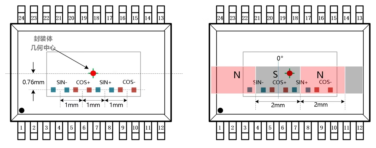
Section 10 gives a package-body length of 7.70–7.90 mm, body width of 4.30–4.50 mm, overall lead span of 6.25–6.55 mm, 0.65 mm lead pitch and maximum overall height of 1.20 mm. These describe different dimensions; use the complete package drawing when preparing the footprint and mechanical clearances.
From Hall sensing to digital position outputs
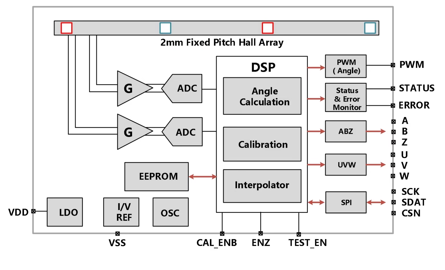
- Hall array and analog front end: the fixed-pitch array generates sine/cosine signals; gain and filtering condition them for digitization.
- ADCs and DSP: the digital chain performs angle calculation, compensation, calibration and interpolation.
- EEPROM and support circuits: integrated nonvolatile storage retains configuration and calibration data; the diagram also includes LDO, reference and oscillator blocks.
- Outputs and monitoring: processed position feeds PWM, ABZ, UVW and SPI, while STATUS and the error-monitoring path report signal or diagnostic conditions.
MT6620 voltage, current, accuracy and dynamic specifications
The following values expand the selection overview using the electrical tables on pp. 7–9. Unless otherwise stated there, the operating conditions are 3.0–5.5 V and −40 to +125°C. A typical value is not a maximum or a guaranteed complete-encoder performance figure.
| Parameter | Datasheet value and condition | Practical interpretation |
|---|---|---|
| Operating supply | 3.0 V minimum, 3.3–5.0 V typical range, 5.5 V maximum | Use the operating range for power design. The 6.5 V absolute-maximum rating is not an operating supply. |
| Supply current | 25 mA typical | Approximate typical IC power is 82.5 mW at 3.3 V or 125 mW at 5.0 V, calculated as V × I. These are typical estimates, not worst-case thermal budgets. |
| Undervoltage alarm | Threshold 2.45–2.65 V; typical hysteresis 100 mV | An alarm threshold below 3.0 V does not extend the specified operating range. |
| Factory-calibrated INL | ±0.5° typical, subject to the datasheet’s test conditions | Keep chip nonlinearity separate from full-ring mechanical-angle error. |
| Customer-calibrated INL | ±0.2° typical; the footnote excludes pole-to-pole magnetization nonuniformity and installation deviation | Validate the completed ring, sensor, mounting and reference system rather than treating this as a finished encoder guarantee. |
| DNL | ±0.05° typical at the 2,500-pulse ABZ setting | Differential nonlinearity describes output-step variation; it is distinct from integral nonlinearity. |
| Transient noise | 0.01° rms typical at 25°C, 100 Gs and BW = 3 | The stated field and bandwidth conditions matter. Digital output resolution alone does not determine usable signal quality. |
| Hysteresis | 0.022° typical; multiple programmable settings | Assess its effect on reversal response and low-speed motion. |
| Startup readiness | 70 ms typical, with the stated supply-rise condition of less than 100 μs | Allow a suitable controller startup interval and verify operation with the actual power ramp. |
| System delay | 5 μs typical under uniform motion | Consider latency in the dynamic position-error budget; it is not a universal end-to-end controller latency. |
| Digital input levels | VIH ≥ 0.8 × VDD; VIL ≤ 0.2 × VDD | Check logic margins when connecting devices powered from different voltage rails. |
| Digital output levels | VOH ≥ VDD − 0.4 V at −2 mA; VOL ≤ 0.4 V at +2 mA | Verify output loading and host input thresholds under the specified test conditions. |
The typical INL, DNL and noise figures are quoted in the chip’s angle/signal context. On a multipole target, confirm how this relates to mechanical shaft angle in the chosen system and measure the full revolution or stroke against an appropriate reference.
MT6620 applications: motors, robot joints and linear axes
Brushless motor feedback
Programmable ABZ and UVW outputs support incremental position feedback and commutation-oriented integration. Match the magnetic target, output configuration, motor electrical cycles and controller input limits.
Robot joint modules
An off-axis arrangement can place the IC beside the rotating magnetic track while retaining a shaft bore for mechanical functions. Confirm the joint’s reference and startup strategy: a repeating multipole ring alone does not identify a unique power-up position over one mechanical revolution.
Linear motors and positioning axes
A 2 mm pole-pitch magnetic scale provides incremental displacement feedback along a moving axis. Review scale length, field uniformity, sensor alignment, end allowances and the required reference system.
Optical scale replacement projects
Magnetic sensing offers a non-contact feedback architecture worth evaluating for selected optical-scale replacement projects. Verify resolution, measured accuracy, reference behavior, interface compatibility and environmental performance before treating a design as an interchangeable replacement.
Explore OTV Sensing’s incremental magnetic rotary encoders and incremental magnetic linear encoders and readheads for related feedback architectures. These are broader product families, not a claim that every listed product uses MT6620.
MT6620 magnet requirements: 2 mm pole pitch and 5–50 mT field
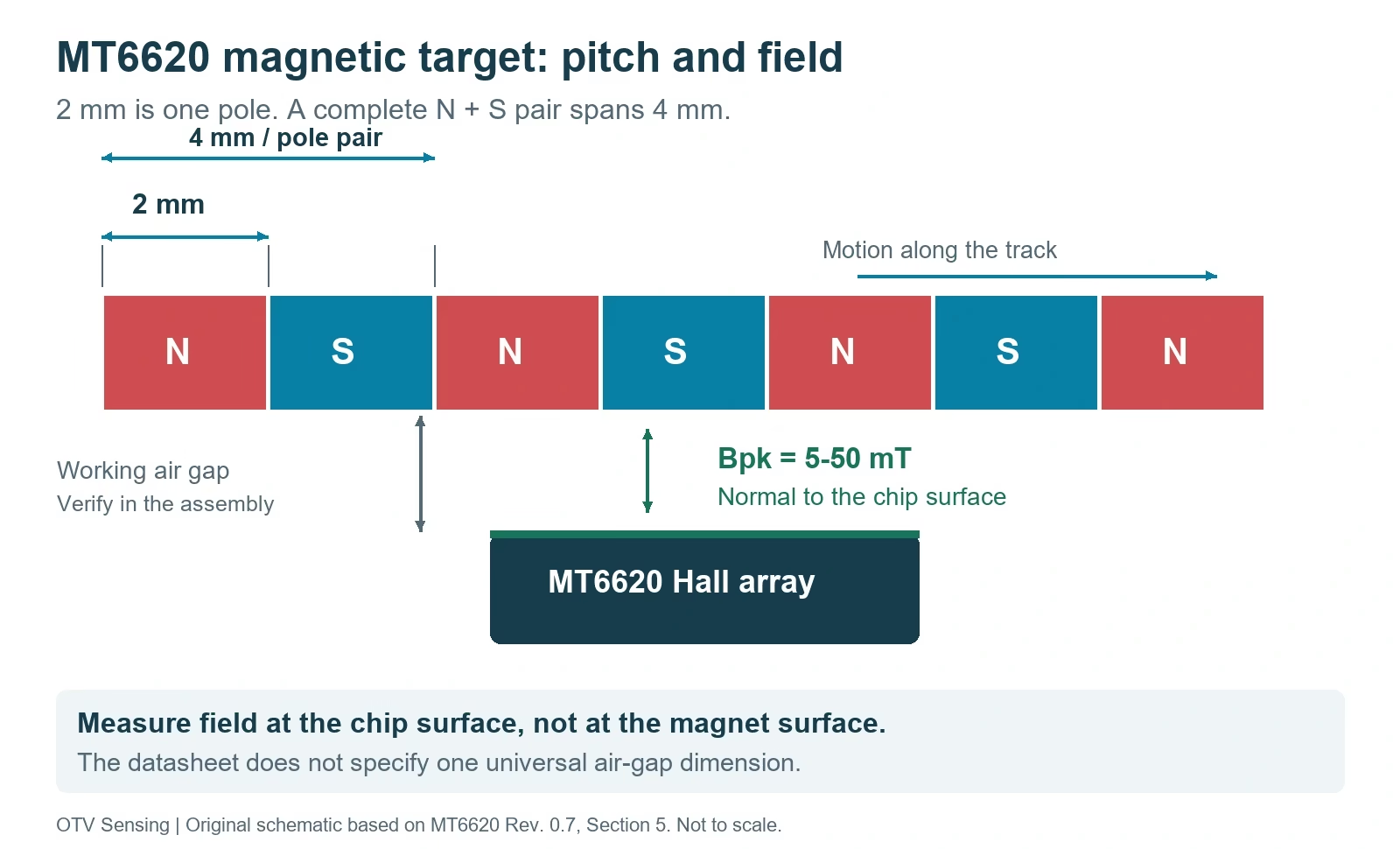
The fixed Hall-array geometry makes magnet matching a central design requirement. Section 5 specifies a radially magnetized multipole ring or a matching magnetic scale. A 2 mm pole pitch describes one N or S region along the sensing path; the full N/S pair spans 4 mm.
| Target requirement | What to specify | What to validate |
|---|---|---|
| Pole pitch | 2 mm per pole; 4 mm per pole pair along the sensing track | Pitch distribution around the full ring or along the working scale length. |
| Magnetization and orientation | Radial multipole ring geometry, or suitable linear scale; field normal to chip surface | Sensor face orientation and usable sine/cosine signals in the assembled system. |
| Field amplitude | Bpk = 5–50 mT at the chip surface | Field over the air-gap, temperature and mechanical tolerance range. |
| Air gap and alignment | Project-specific gap, runout, concentricity, tilt and sensor position | The supplied sheet does not provide one universal air-gap value or a complete tolerance envelope. |
| Magnetic material / carrier | Material, temperature range, ring section and carrier drawing | Field strength, temperature drift, fixation and the carrier’s effect on the magnetic circuit. |
Manufacturer illustration: MT6620 and its matching magnetic ring
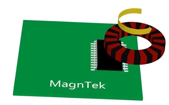
A magnet’s surface field is not the same as the field seen by the IC. A ring that meets its own material specification can still produce unsuitable signals if the chip is too far away, incorrectly oriented, tilted or exposed to nearby motor fields. Select material and magnetization together, then verify the normal field component at the installed sensor.
Matching a magnetic ring: pole count, diameter and sensor position
For a first geometric check, let N be the number of pole pairs on a circular magnetized track. With a nominal 4 mm pole-pair arc length, the track circumference is approximately 4N mm, giving Dtrack = 4N/π mm. This is a derived geometry relation, not a manufacturer-approved ring catalogue.
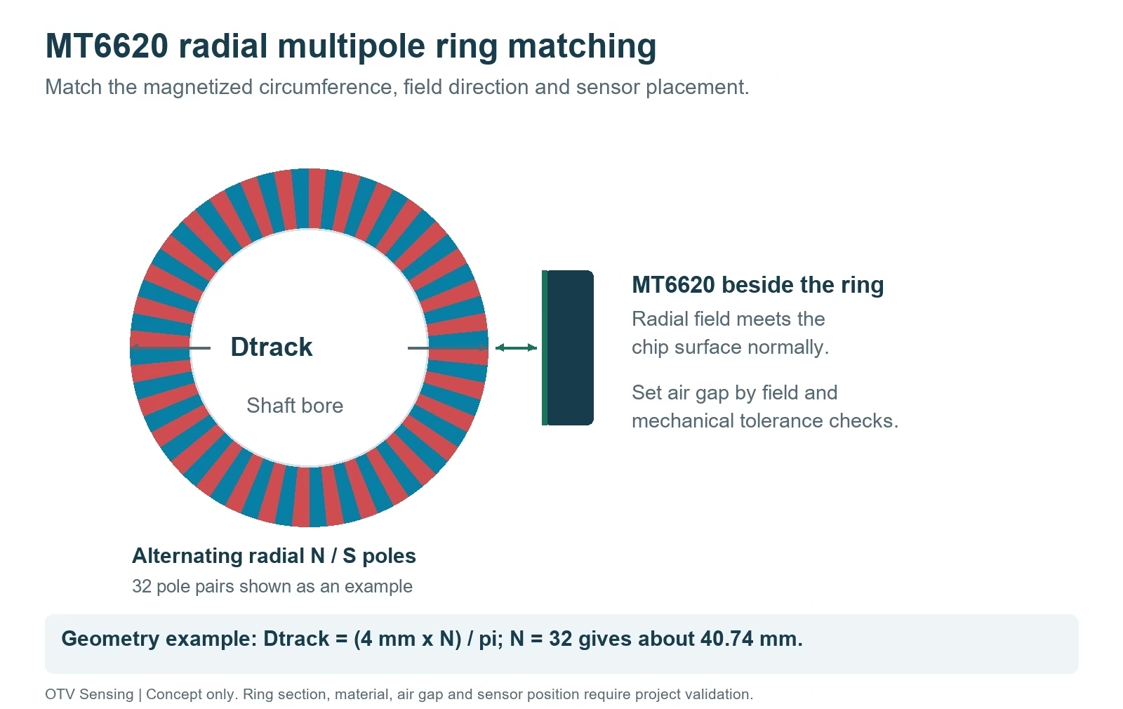
The drawing must identify the magnetized sensing surface, pole count, bore, outside dimensions, thickness, sensor reference plane and PCB location. Do not reuse an axial dual-track Nonius ring merely because another encoder also mentions a 2 mm pole width: magnetization, field direction, track layout and decoding architecture must all match.
OTV Sensing can review the magnetic target as part of a custom magnetic encoder ring project. Linear projects can start from the magnetic linear scale and encoder tape range, with MT6620 compatibility assessed for the actual target.
MT6620 outputs: resolution, speed and absolute-position limits
MT6620 can provide ABZ, UVW, PWM and 3-wire SPI through its dedicated signal pins. Select the outputs according to the drive, position controller and diagnostic needs, then check their timing and electrical compatibility together.
| Output / interface | Resolution and signal details | Pins and integration notes |
|---|---|---|
| ABZ quadrature | 1–2,500 AB cycles per magnetic pole pair, programmable in integer steps; up to 10,000 counts per pole pair with four-edge decoding. A/B frequency specified up to 8 MHz. | A: pin 18; B: pin 17; Z: pin 16. ENZ on pin 10 controls whether the target Z pulse is passed through. |
| Z index configuration | Programmable zero position and pulse width. Width settings include 1, 2, 4, 8, 16, 32, 64 or 128 LSBs, and 60°, 120° or 180°. | The pattern repeats on a uniform multipole target. A unique mechanical index requires a corresponding reference and gating design. |
| UVW | Three signals separated by 120° in the output electrical cycle; programmable 1–63 setting. | U: pin 21; V: pin 22; W: pin 23. Check the selected output cycles against magnetic target periods and motor pole pairs. |
| PWM angle | 12-bit, 4,096-level phase output; programmable polarity and nominal frequency from 125 Hz to 2 kHz. The frequency table gives ±5% limits. | PWM: pin 1. This single-wire push-pull output carries the repeating magnetic-period phase. |
| 3-wire SPI | Angle, temperature and diagnostics; configuration read/write; optional safety word with diagnostic bits and CRC. Minimum SCK period 125 ns corresponds to an 8 MHz clock ceiling from the timing table. | SDAT: pin 13, bidirectional; SCK: pin 14; CSN: pin 15. Implement data-direction turnaround and the specified sampling edges. |
| STATUS / alarm | STATUS indicates signal amplitude during normal operation and calibration state during self-calibration. Alarm reporting covers weak/strong field, overspeed, EEPROM check, calibration failure and undervoltage. | STATUS: pin 19; the pin table labels pin 20 ERROR, while Section 7.5 calls the alarm output FAULT. Follow the applicable pin definition when creating the schematic. |
ABZ pulses and mechanical resolution
If P is the configured AB pulses per magnetic pole pair and the ring has N pole pairs, the nominal output is P × N AB cycles per mechanical revolution. A controller decoding all four edges counts 4PN steps per revolution. At P = 2,500 and N = 32, that is 80,000 AB cycles or 320,000 decoded counts per revolution. These are calculated output increments, not measured angular accuracy.
For a linear 4 mm pole-pair period, four-edge decoding at P = 2,500 gives a nominal step of 4 mm / 10,000 = 0.4 μm. That digital increment does not establish submicron positioning accuracy.
Bandwidth and reference signals
The specified A/B frequency limit is 8 MHz. For a rotating ring, fAB = P × N × rpm / 60. At P = 2,500 and N = 32, the frequency calculation reaches 8 MHz at 6,000 rpm. This is an output-bandwidth example; it is not an independently validated speed rating for a magnetic ring or complete encoder.
With ENZ held high, the datasheet describes a Z pulse for each magnetic pole pair. A unique once-per-mechanical-revolution index requires an appropriate external reference and ENZ gating strategy. Discuss reference-mark magnetic target requirements as part of the whole sensing design.
SPI and PWM are not a unique full-ring code
SPI and PWM provide an absolute phase/angle reading within the repeating magnetic pattern. On a uniform multipole ring, equivalent positions in different pole pairs produce the same phase. A unique shaft position over an entire revolution, or a unique position over a long scale, needs additional position information or a different target architecture.
Firmware detail: the overview describes a 16-bit SPI angle value, while the revised Section 7.4.3 shows ANGLE[16:0] across two registers when DATA_FLAG = 0, and a different arrangement when a refresh flag is enabled. Follow the actual register layout and confirm the applicable revision rather than using a bit-count headline as a system specification.
MT6620 calibration and magnetic target validation
The supplied sheet lists typical INL figures of ±0.5° after factory calibration and ±0.2° after customer self-calibration. Its footnote excludes pole-to-pole magnetization nonuniformity and installation deviation from the latter figure. These values should not be presented as a guaranteed mechanical-angle accuracy for a complete multipole ring assembly.
- Fix the final assembly: set the chip, ring or scale in the intended mechanical positions before calibration.
- Check magnetic signals: verify the normal field component and STATUS response across the working range. The normal-operation guidance gives a suitable STATUS duty-cycle region of 10–33%; the separate strong-field alarm threshold is above 44%. These are different criteria.
- Run the specified motion: self-calibration permits nonuniform continuous motion. The stated rotary range is 40–3,000 magnetic pole pairs per minute, with at least 16 pole pairs traversed. Divide by ring pole-pair count to obtain mechanical rpm. The linear range is 0.16–12 m/min, again covering at least 16 pole pairs.
- Trigger and verify completion: use CAL_ENB or SOFT_AUTOCAL and observe STATUS or CAL_STATE. After calibration ends, wait at least 500 ms before releasing the trigger as described in the sheet. A failed attempt requires a power cycle before retrying.
- Measure the completed encoder: evaluate the full mechanical revolution or working stroke, reference behavior, repeatability, dynamic error and temperature performance.
The calibration speed is specified in magnetic pole pairs per minute, not directly in shaft rpm. For a 32-pole-pair example, 40–3,000 pole pairs/min corresponds to 1.25–93.75 mechanical rpm. Keep calibration requirements separate from normal operating-speed calculations.
OTV Sensing support: from magnetic rings to MT6620 chip sourcing
OTV Sensing can coordinate magnetic ring or scale customization and encoder chip sourcing for an MT6620-based design. Reviewing the target and IC together helps avoid selecting a mechanically convenient ring whose pitch, magnetization or field does not suit the sensor.
Magnetic target review
Define the radial multipole pattern or linear scale pitch, geometry, material, carrier, magnetized surface and field target. Agree the required sample measurements and acceptance criteria.
Chip and integration review
Confirm the MT6620 ordering code, package, interface configuration, reference strategy and calibration needs. Chip availability, quantities and delivery dates are confirmed with the quotation.
Use the magnetic encoder IC supply and selection page for broader sourcing requirements. For a useful project review, send:
- Target application, rotary or linear motion, maximum speed, working temperature and motor-field environment.
- Ring or scale drawing: bore, magnetized track diameter, thickness, carrier, pole pairs, air gap and sensor orientation.
- Required ABZ/PWM/SPI/UVW behavior, controller input limits, homing or index strategy and startup requirements.
- Measured-accuracy and repeatability targets, sample quantity, expected annual volume and chip quantity.
Specify the MT6620 chip and magnetic target together
Share your ring drawing or linear-axis envelope with OTV Sensing. We can review the 2 mm pole-pitch target, mounting and field requirements, then coordinate a proposal covering magnetic components and MT6620 chip sourcing.
Request an MT6620 chip and magnetic ring reviewMT6620 magnetic encoder and ring matching FAQ
Does MT6620 need a 2 mm or 4 mm pole pitch?
The supplied specification uses 2 mm for a single magnetic pole. One N/S pole pair occupies 4 mm along the sensing path. State both values on the target drawing to avoid ambiguous pitch terminology.
Can any 2 mm pole-width magnetic ring work with MT6620?
No. The radial magnetization, field component at the chip, sensor orientation, track geometry and mechanical tolerances also need to match. An axial Nonius target from a different chip family is not automatically compatible.
What air gap should I use?
The supplied sheet specifies a 5–50 mT normal field at the chip surface but does not provide a universal air-gap dimension. Determine a workable gap from the chosen magnet, ring section, mounting arrangement and tolerance tests.
Is MT6620 a full-revolution absolute encoder on a multipole ring?
A uniform multipole track repeats its phase in every pole pair. SPI or PWM alone therefore does not identify which pole pair is being read. The system needs an additional reference or position architecture for unique mechanical position.
Can OTV Sensing quote the ring and chip together?
Yes. Submit the target drawing, required outputs, sample and annual quantities, and MT6620 chip quantity. Magnetic target compatibility, chip availability, commercial terms and sample validation are confirmed for the project.
Source and engineering notes
Primary source: supplied MagnTek MT6620 — High-Precision Off-Axis Magnetic Linear Position and Angle Encoder IC, Rev. 0.7, May 2023. Features and applications: p. 1; operating parameters: pp. 7–9; magnetic target requirements: p. 10; outputs and SPI: pp. 12–23; calibration: pp. 24–25. Figures 1, 2 and the ring arrangement from Figure 4 are extracted from the supplied manufacturer datasheet and credited in their captions. The additional pitch/field and radial-ring schematics, and numerical geometry examples, are original OTV Sensing explanations. Request the applicable manufacturer specification and register documentation before design release.