Off-Axis Absolute Encoders: Axial & Radial
Choose the reading direction first. Then match the ring, readhead and controller.
Compare axial face-reading OME / OMEC and radial outer-edge-reading OMR / OMER encoders. Start with the space around your shaft, then select a complete module or discuss a chip-and-magnetic-ring solution for your own electronics.
Open-centre magnetic feedback · Family-specific specifications · Components or modules
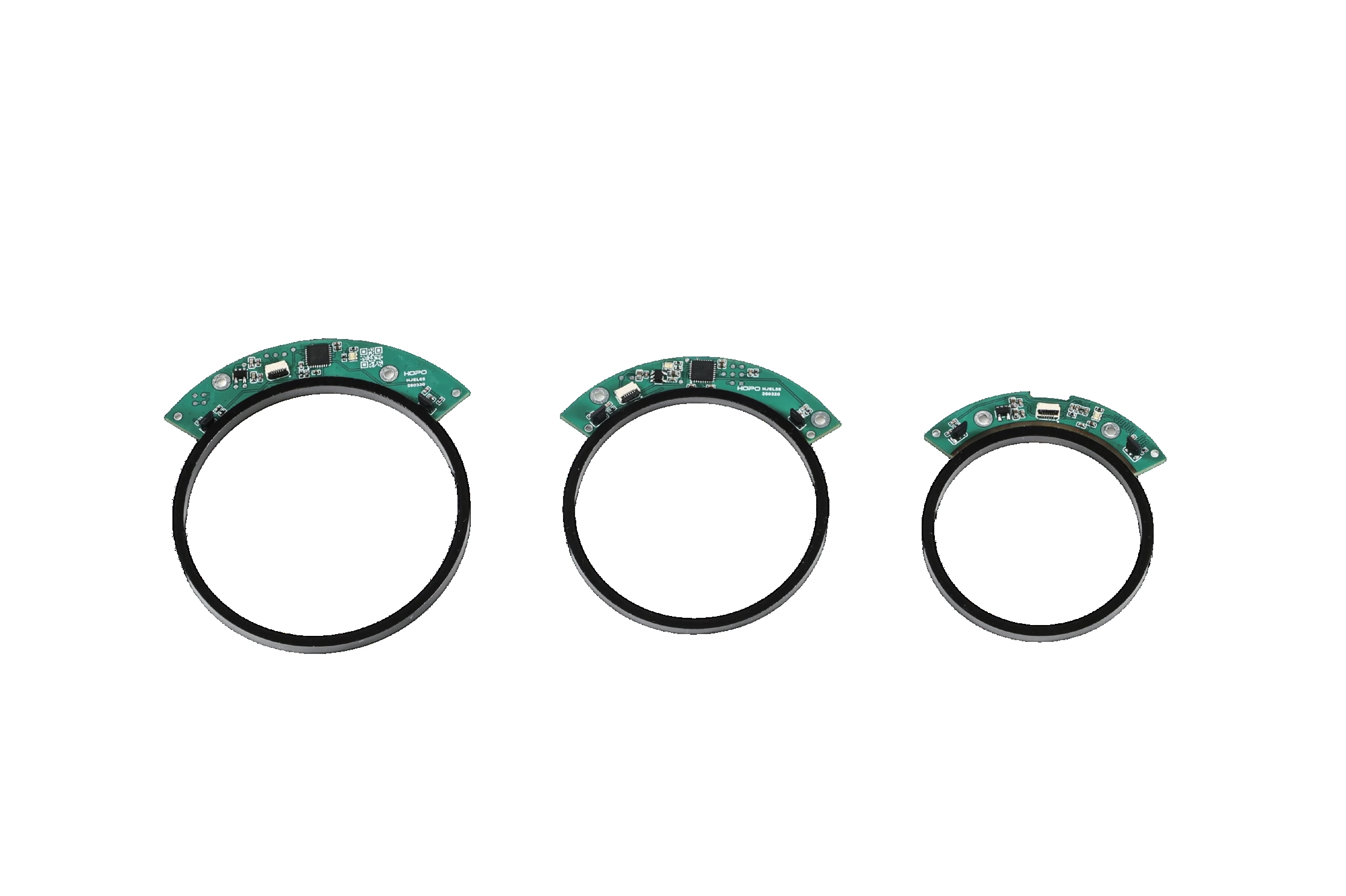
What is an off-axis absolute encoder?
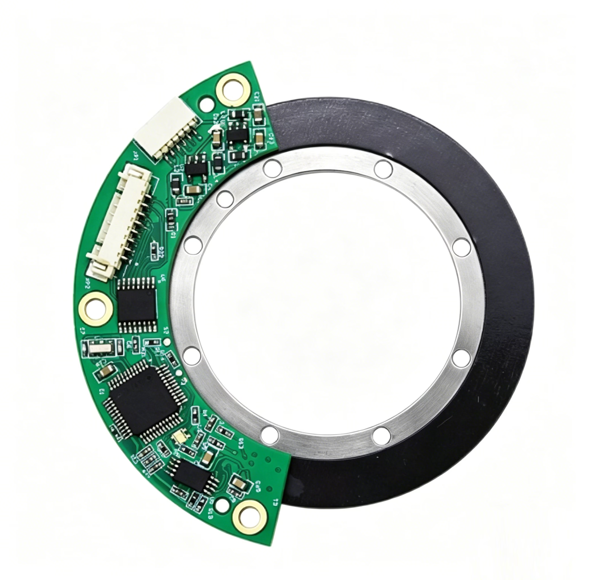
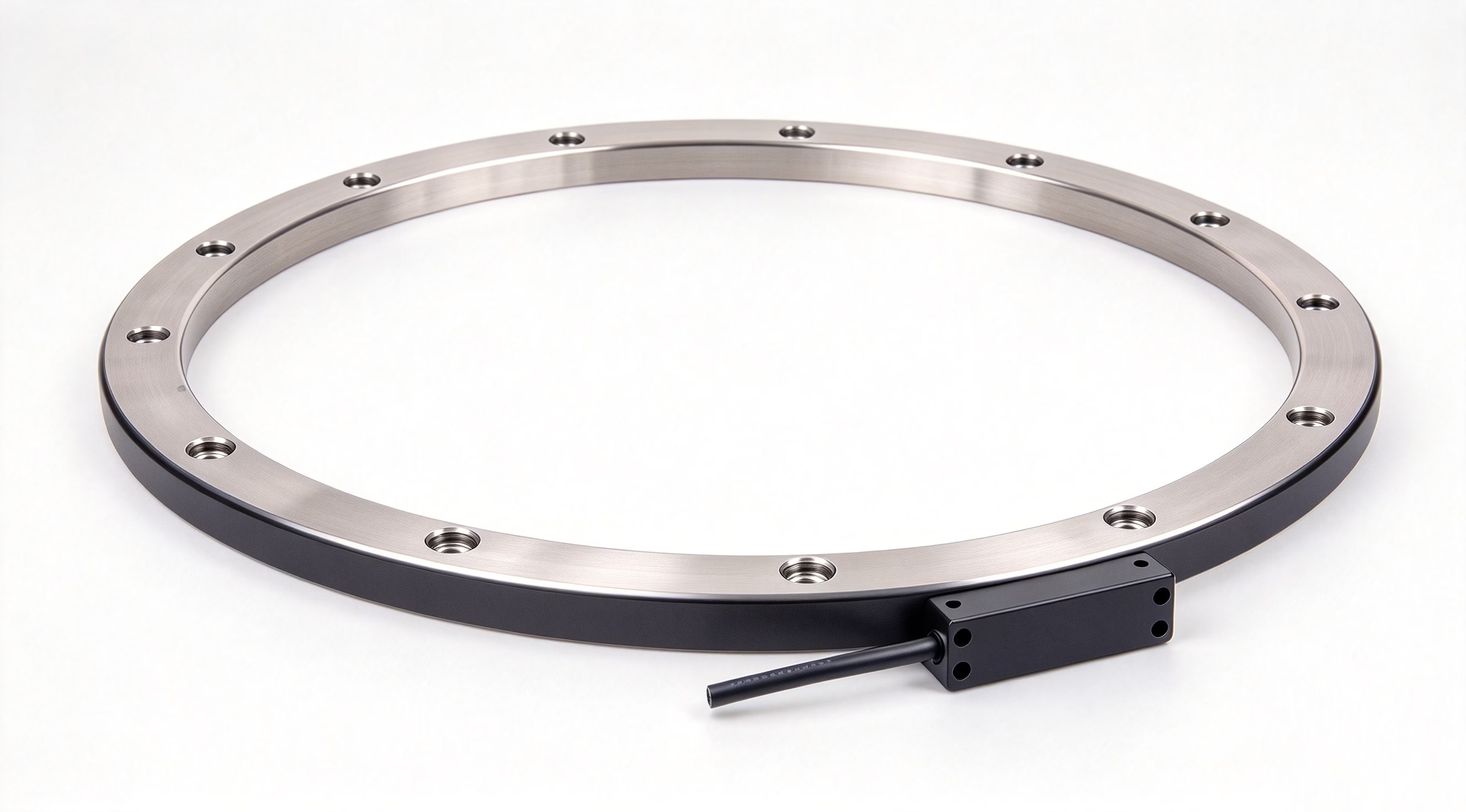
An off-axis absolute encoder measures shaft angle with a stationary sensor positioned away from the shaft centreline. A matched magnetic ring rotates with the shaft, leaving a central opening. Absolute angle is determined from the coded magnetic reference rather than solely by accumulating incremental pulses.
“Off-axis” describes the sensor’s offset from the rotation axis. “Axial” and “radial” below describe which surface of the ring the readhead faces; they do not by themselves specify the magnetic pattern or make different rings interchangeable.
Axial off-axis absolute encoders
The readhead faces the ring’s flat end surface. Start here when the ring face is accessible and axial clearance is available for the sensing gap, PCB or housing.
Explore OME and OMEC →Radial off-axis absolute encoders
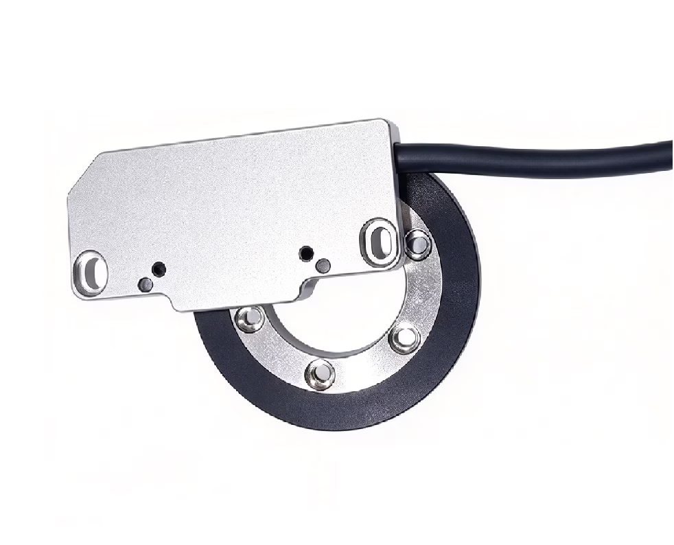
The readhead faces the outer circumference. Start here when the ring’s outer edge is accessible and the design has radial clearance for the readhead and its cable or connector.
Explore OMR and OMER →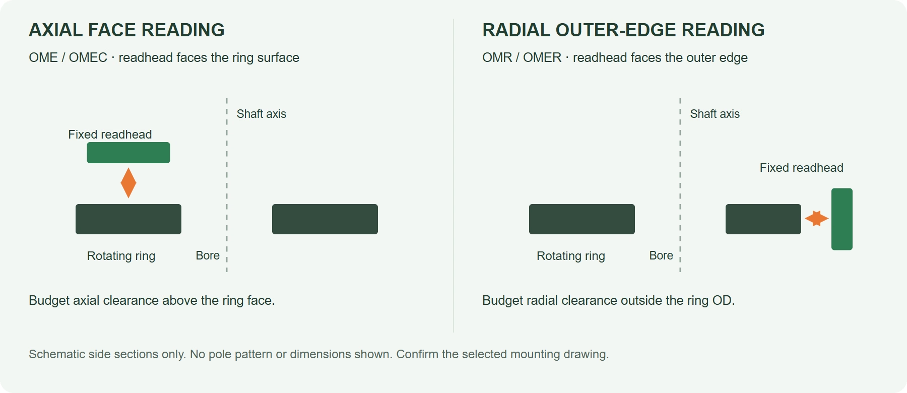
Swipe to view the complete schematic →
Compare axial and radial hollow-shaft absolute encoders
Choose a family by mounting geometry, mechanical envelope, controller interface and the required positioning accuracy. Published resolution, accuracy and protection values apply to their stated family or configuration—not to every encoder on this page.
Swipe horizontally to compare all columns →
| Family / reading | Published ring ID / OD range | Resolution & accuracy reference | Interfaces / integration fit | Readhead / protection |
|---|---|---|---|---|
| OME Axial face | Ring ID 6–65 mm Ring OD 22–84 mm | 17–20-bit by model Max. static error ±0.1° | SSI, BiSS-C or SPI by configuration; ABZ may be an additional incremental output | PCB integration; protect the electronics in the host design |
| OMEC Axial face | Ring ID 25–65 mm Ring OD 49 or 84 mm | 16–20-bit by configuration System accuracy ±0.1° under specified mounting conditions | BiSS-C, SSI, SPI or Tamagawa; verify the selected electrical interface | Thin-profile configured system; IP67 applies to the specified installation |
| OMR Radial outer edge | Ring ID 60–285 mm Ring OD 81.53–325.94 mm | Published resolution down to 0.1 arcsecond* Published absolute accuracy ≤0.05°* | BiSS-C / SSI via RS422; MODBUS-RTU / Tamagawa via RS485 | Aluminium housed readhead; published IP67 configuration |
| OMER Radial outer edge | Ring ID 38.8–60 mm Ring OD 43.8–65 mm | 14-bit SPI Listed positioning accuracy 0.396° worst / 0.374° average | 5 V supply, 3.3 V SPI logic; curved PCB and matched ring | Open PCB requires customer protection; ring-only ratings do not protect the readhead |
* OMR values are published configuration references. Specifications use different test conditions and terminology; this table is not a test under identical conditions. Nominal ring ID is not a guarantee of usable assembled bore clearance.
Find a ring size: compare 24 listed configurations
Screen nominal ring dimensions, then request the approved readhead and mounting drawing. Interface entries indicate family configuration options, not all outputs simultaneously. OME model suffixes do not always equal the listed target-ring ID.
24 listed configurations. Check full dimensions before design release.
Swipe horizontally for ring size and interface columns →
| Model / ring configuration | Reading | Ring ID mm | Ring OD mm | Resolution | Absolute interface options |
|---|---|---|---|---|---|
| OME06 | Axial | 6 | 22 | 17-bit | SPI / BiSS-C / SSI |
| OME08 | Axial | 10 | 22 | 18-bit | SPI / BiSS-C / SSI |
| OME10 | Axial | 10 | 29 | 17–18-bit | SPI / BiSS-C / SSI |
| OME15 | Axial | 15 | 29 | 17–18-bit | SPI / BiSS-C / SSI |
| OME20 | Axial | 20 | 39 | 17–19-bit | SPI / BiSS-C / SSI |
| OME25 | Axial | 25 | 49 | 17–19-bit | SPI / BiSS-C / SSI |
| OME35 | Axial | 35 | 55 | 17–20-bit | SPI / BiSS-C / SSI |
| OME45 | Axial | 45 | 64 | 17–20-bit | SPI / BiSS-C / SSI |
| OME65 | Axial | 65 | 84 | 17–20-bit | SPI / BiSS-C / SSI |
| OMEC-ID25 · 4-hole | Axial | 25 | 49 | 16–20-bit | SPI / BiSS-C / SSI / Tamagawa |
| OMEC-ID25 · 6-hole | Axial | 25 | 49 | 16–20-bit | SPI / BiSS-C / SSI / Tamagawa |
| OMEC-ID31.5 | Axial | 31.5 | 49 | 16–20-bit | SPI / BiSS-C / SSI / Tamagawa |
| OMEC-ID62 | Axial | 62 | 84 | 16–20-bit | SPI / BiSS-C / SSI / Tamagawa |
| OMEC-ID65 | Axial | 65 | 84 | 16–20-bit | SPI / BiSS-C / SSI / Tamagawa |
| OMR + ME-MRR-082 | Radial | 60 | 81.53 | Down to 0.1 arcsec* | BiSS-C / SSI / MODBUS-RTU / Tamagawa |
| OMR + ME-MRR-122 | Radial | 100 | 122.29 | Down to 0.1 arcsec* | BiSS-C / SSI / MODBUS-RTU / Tamagawa |
| OMR + ME-MRR-163 | Radial | 140 | 162.97 | Down to 0.1 arcsec* | BiSS-C / SSI / MODBUS-RTU / Tamagawa |
| OMR + ME-MRR-204 | Radial | 174 | 203.82 | Down to 0.1 arcsec* | BiSS-C / SSI / MODBUS-RTU / Tamagawa |
| OMR + ME-MRR-223 | Radial | 190 | 229.18 | Down to 0.1 arcsec* | BiSS-C / SSI / MODBUS-RTU / Tamagawa |
| OMR + ME-MRR-326 | Radial | 285 | 325.94 | Down to 0.1 arcsec* | BiSS-C / SSI / MODBUS-RTU / Tamagawa |
| OMER-ID38.8 | Radial | 38.8 | 43.8 | 14-bit | SPI |
| OMER-ID45 | Radial | 45 | 50 | 14-bit | SPI |
| OMER-ID53 | Radial | 53 | 58 | 14-bit | SPI |
| OMER-ID60 | Radial | 60 | 65 | 14-bit | SPI |
No listed ring configuration matches these filters. Send your bore, envelope and controller requirements for an engineering review.
Axial off-axis absolute rotary encoder options
OME: PCB modules across multiple ring sizes
Compare OME when you need an OEM PCB layout around a hollow shaft. The published model table covers ring IDs from 6 to 65 mm, with model-dependent 17–20-bit resolution and a 5 V ±5% supply.
- Separated rotating target and stationary PCB.
- Published current ≤100 mA; verify the selected configuration.
- Most listed models use a 0.5 ±0.1 mm chip-to-target gap; OME20 lists 1.3 ±0.1 mm.
OMEC: configured thin-profile systems
Compare OMEC when you need a thin-profile axial layout with a configured readhead, connector and cable. Listed bores are 25, 31.5, 62 and 65 mm; the two ID25 mounting patterns are separate configurations.
- 16–20-bit single-turn absolute configurations.
- Published no-load current <85 mA at 25°C, on a 5 V ±5% supply.
- Confirm the exact IP67 assembly, connector sealing and complete installed thickness.
Radial off-axis absolute rotary encoder options
OMR: housed readheads and larger rings
Compare OMR for industrial controller connections and larger magnetic rings. Its standard-ring table spans nominal IDs of 60–285 mm, with a published readhead housing of 53 × 14 × 12.5 mm.
- BiSS-C, SSI, MODBUS-RTU or Tamagawa options.
- 5 V ±5%; published no-load current <160 mA at 25°C.
- Optimal published sensing gap 0.3 ±0.1 mm; maximum ≤0.6 mm.
OMER: thin magnetic rings with 14-bit SPI
Compare OMER for a small ring envelope and embedded SPI integration. Four standard configurations have nominal ring IDs of 38.8, 45, 53 and 60 mm, with ring thicknesses of 3–4 mm.
- 14-bit / 16,384 positions per revolution.
- 5 V ±5% supply; 3.3 V SPI logic; <25 mA no-load current at 25°C.
- Recommended sensing gap 1.0 ±0.2 mm; protect the open PCB in the host enclosure.
From encoder chips and magnetic rings to complete modules
OTV Sensing supports different integration routes. A component quotation is not a complete encoder performance guarantee: define the selected IC, magnetic target, electronics and mechanical installation together.
1. Encoder IC supply and selection
For teams designing their own electronics, discuss the sensing geometry, absolute data format, supply and electrical levels before choosing the IC.
Explore magnetic encoder ICs →iC-Haus solution references provide an additional starting point; availability and the exact configuration require confirmation.
2. Matched magnetic rings and targets
For an existing readhead design, specify ring ID/OD, the reading surface, track geometry, pole pattern and magnetic field requirements at the operating gap.
Explore magnetic rings and discs →Need a different geometry? Request a custom magnetic target review.
3. Readhead-and-ring modules
For a matched feedback assembly, choose an OME, OMEC, OMR or OMER configuration and verify the complete mounting and controller connection.
Return to the four-family comparison →Send speed, accuracy, bore and controller requirements with the drawing.
How to select an off-axis absolute encoder
- Choose the reading surface: axial face access or radial outer-edge access.
- Budget the whole envelope: ring ID/OD, readhead, sensing gap, fixing method and cable clearance.
- Specify the feedback: single-turn or a verified multiturn requirement, angular accuracy, speed and update timing.
- Match the controller: protocol, logic or differential electrical levels, frame format and startup behavior.
- Validate the installation: runout, eccentricity, stray fields, temperature, sealing and calibration.
Keep these specifications separate
Resolution is not accuracy. OMER’s 14-bit output has an approximately 0.022° step, while its published positioning accuracy uses separate worst/average figures. A higher bit count alone does not establish installed accuracy.
Ring thickness is not assembly height. Include the readhead and all required clearances. OMER’s IP67 and up-to-600-bar catalogue statements apply to the magnetic ring only; they do not rate the PCB or complete encoder for pressure.
Agree operating media, temperature and test conditions before relying on a pressure claim.
Use the off-axis magnetic ring design guide for target geometry, and the hollow-shaft encoder assembly and calibration guide for mounting checks. Final selection requires the approved model drawing and installation instructions.
Off-axis absolute encoder selection FAQ
Is a hollow-shaft encoder always an off-axis absolute encoder?
No. Hollow-shaft describes the mechanical opening; off-axis describes sensor placement; absolute describes the position information. Check all three independently. An encoder with only ABZ pulses does not provide an absolute angle word by itself.
Which OTV families read axially and which read radially?
For the configurations compared here, OME and OMEC face the magnetic ring’s axial surface. OMR and OMER read from the outer circumference. Always follow the selected ring/readhead mounting drawing rather than inferring sensor placement from the ring’s magnetisation label alone.
Should I choose axial or radial reading for a robot joint?
Start with the available mounting space and access to the sensing surface. Axial face reading needs clearance over the ring face; radial reading needs space outside its OD. Then verify required accuracy, speed, controller timing, protection and stray-field conditions in the joint.
Can OTV supply only the magnetic ring or the encoder chip?
Yes, component supply and matched module solutions are separate routes. Discuss encoder IC selection or a target-only project with OTV Sensing. Compatibility, stock and performance must be confirmed for the exact IC, ring pattern and operating gap.
Can I exchange rings between OME, OMEC, OMR and OMER?
Do not assume interchangeability from the same bore size. Magnetic coding, track geometry, field requirements, readhead orientation, gap and signal processing must match. Request a compatibility review using both drawings and the selected readhead specification.
What information makes an encoder quotation useful?
Send ring ID and maximum OD, axial/radial envelope, reading direction, angular accuracy, resolution, speed, controller protocol and electrical levels, environment, quantity and target schedule. Include whether you need an IC, a passive ring or a matched readhead-and-ring module.
Find the right ring, chip or encoder module
Share your shaft and housing drawing, feedback requirements and controller interface. We will help narrow the axial or radial configuration to evaluate.
IC / ring / module · ring ID and OD · installation space · accuracy · speed · interface · quantity