
Radial Hollow-Shaft Absolute Encoders
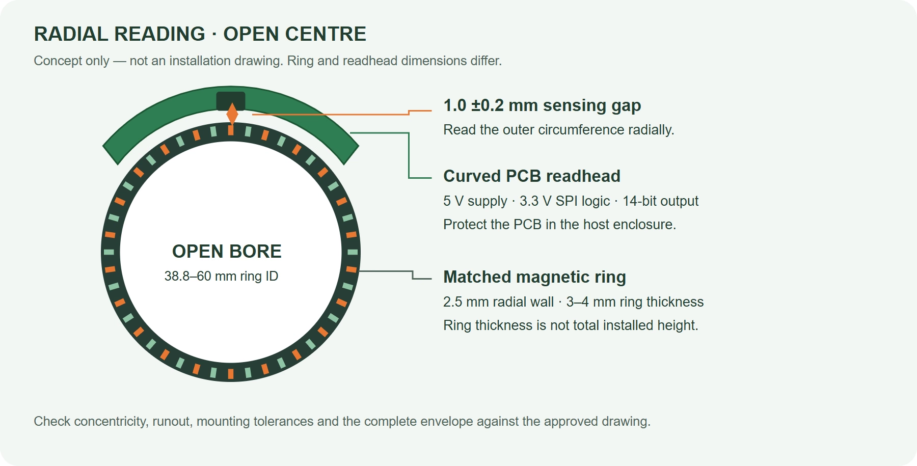
Keep the shaft centre open. Read absolute position from the magnetic ring’s outer edge.
OTV Sensing supplies matched radial encoder kits with 14-bit SPI output and four nominal ring bores from 38.8 to 60 mm. Choose the ring geometry for your mechanism, then verify the mounting envelope with us.
Single-turn absolute feedback · 5 V supply · Customer-protected readhead
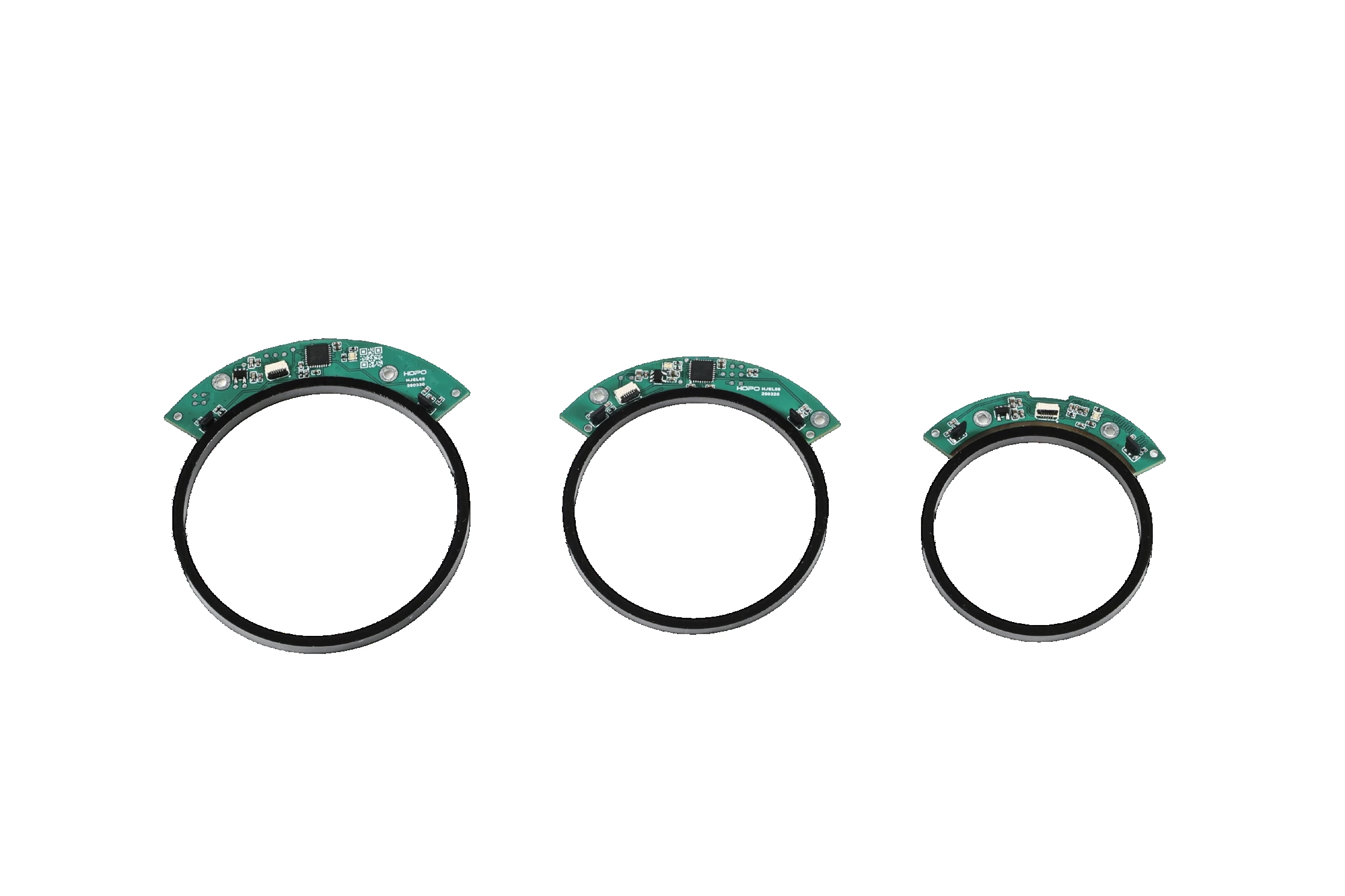
Absolute feedback around a hollow shaft
Leave a route through the centre
Route cables, pneumatic lines or other services through the ring’s centre when the surrounding mechanism permits. No encoder shaft occupies that central space.
Use the outer circumference
A curved PCB readhead senses the ring radially. This layout is worth evaluating when the ring’s outer edge is accessible and the host design needs an open centre.
Keep sensing components together
Specify the magnetic ring and readhead as a matched pair. Ring magnetisation, track geometry and readhead position must suit each other; bore size alone does not establish compatibility.
Compare four hollow-shaft absolute encoder sizes
All four models share the same listed resolution, SPI interface, accuracy and speed. The differences below are mechanical: nominal ring bore, outer diameter and ring thickness.
| OTV model | Ring bore ID | Ring OD | Ring thickness | Selection highlight |
|---|---|---|---|---|
| OTV-OMER-ID38.8 | 38.8 mm | 43.8 mm | 4 mm | Smallest outer diameter |
| OTV-OMER-ID45 | 45 mm | 50 mm | 3.5 mm | Intermediate bore; 50 mm OD |
| OTV-OMER-ID53 | 53 mm | 58 mm | 3 mm | Thinnest ring in this series |
| OTV-OMER-ID60 | 60 mm | 65 mm | 4 mm | Largest nominal ring bore |
All ring dimensions are nominal. Each ring has a calculated radial wall width of 2.5 mm: (OD − ID) / 2. Retaining features, tolerances and the readhead envelope must be checked separately.
14-bit SPI magnetic ring encoder specifications
| Parameter | Listed value |
|---|---|
| Position output | Single-turn absolute; 14-bit / 16,384 positions per revolution |
| Interface / logic | SPI / 3.3 V logic level |
| Supply / no-load current | 5 V ±5% / <25 mA at 25°C |
| Maximum operating speed | 5,000 rpm |
| Recommended sensing gap | 1.0 ±0.2 mm |
| Positioning accuracy, listed | 0.396° worst; 0.374° average |
| Repeatability, listed | 0.154° worst; 0.146° average |
| Maximum SPI clock | 10 MHz; this is not the position update rate |
| Temperature / humidity | −20 to +80°C / maximum 70% RH, non-condensing |
| External magnetic field, listed | ±0.5 mT |
| Connection | 6-pin FPC connector; 0.5 mm pitch |
| Output load current / ESD | 20 mA / SPI HBM ±2 kV |
Radial encoder integration: gap, wiring and protection
Mechanical setup
- Confirm the ring bore, outer diameter and retaining method against your shaft and housing.
- Target the specified 1.0 ±0.2 mm readhead-to-ring sensing gap. Include runout, concentricity and thermal movement in the tolerance review.
- Request the installation drawing before freezing the PCB pocket or total assembly height.
- Plan calibration access. The listed minimum calibration speed is 20 rpm; this is not a minimum operating speed.
5 V power, 3.3 V SPI signals
Supply voltage and communication logic are different specifications. Check the controller’s input/output compatibility before connection.
| Pin | Signal |
|---|---|
| 1 | NCS |
| 2 | SCLK |
| 3 | MOSI |
| 4 | MISO |
| 5 | GND |
| 6 | VIN (+5 V) |
Request the mating-connector orientation, SPI timing, command framing and calibration procedure for the selected kit.
Where a radial hollow-shaft encoder can fit
Compact rotary mechanisms
Evaluate open-centre indexing units and rotary actuators where cables or services must pass through the axis and the outer ring edge is accessible.
Robot and automation joints
Consider single-turn joint-position feedback where the listed accuracy meets the control requirement. Review motor stray fields, runout and host protection before selection.
OEM embedded equipment
Combine an existing 5 V rail with 3.3 V SPI logic and a separate readhead pocket. Verify real bus timing and mounted performance in the prototype.
Application examples are engineering evaluation scenarios, not certifications or guaranteed suitability for safety functions.
Choose the encoder architecture that fits your system
Need higher resolution or another interface?
Compare our OMEC off-axis absolute magnetic encoders for other configured resolutions and interface options. OTV-OMER is the radial 14-bit SPI family on this page; the families have different mounting and specification requirements.
Need a different sensing principle or signal?
Explore hollow inductive encoders for an alternative sensing approach, or incremental magnetic rotary encoders for incremental output. These are separate products, not selectable OTV-OMER options.
For a passive target rather than a complete feedback kit, see magnetic rings and encoder disks. Our off-axis magnetic ring design guide explains the geometry and matching questions to resolve.
OTV-OMER vs OMR: which radial absolute encoder fits?
Both families measure absolute rotary angle by reading a magnetic ring radially. Choose between them by readhead construction, ring envelope, controller interface and the required accuracy—not by the word “radial” alone.
OTV-OMER: thin rings + SPI readhead
Evaluate this series when your OEM design can protect an open PCB and uses 3.3 V SPI logic. Four ring sizes provide 38.8–60 mm nominal bores and 3–4 mm ring thickness, with 14-bit output.
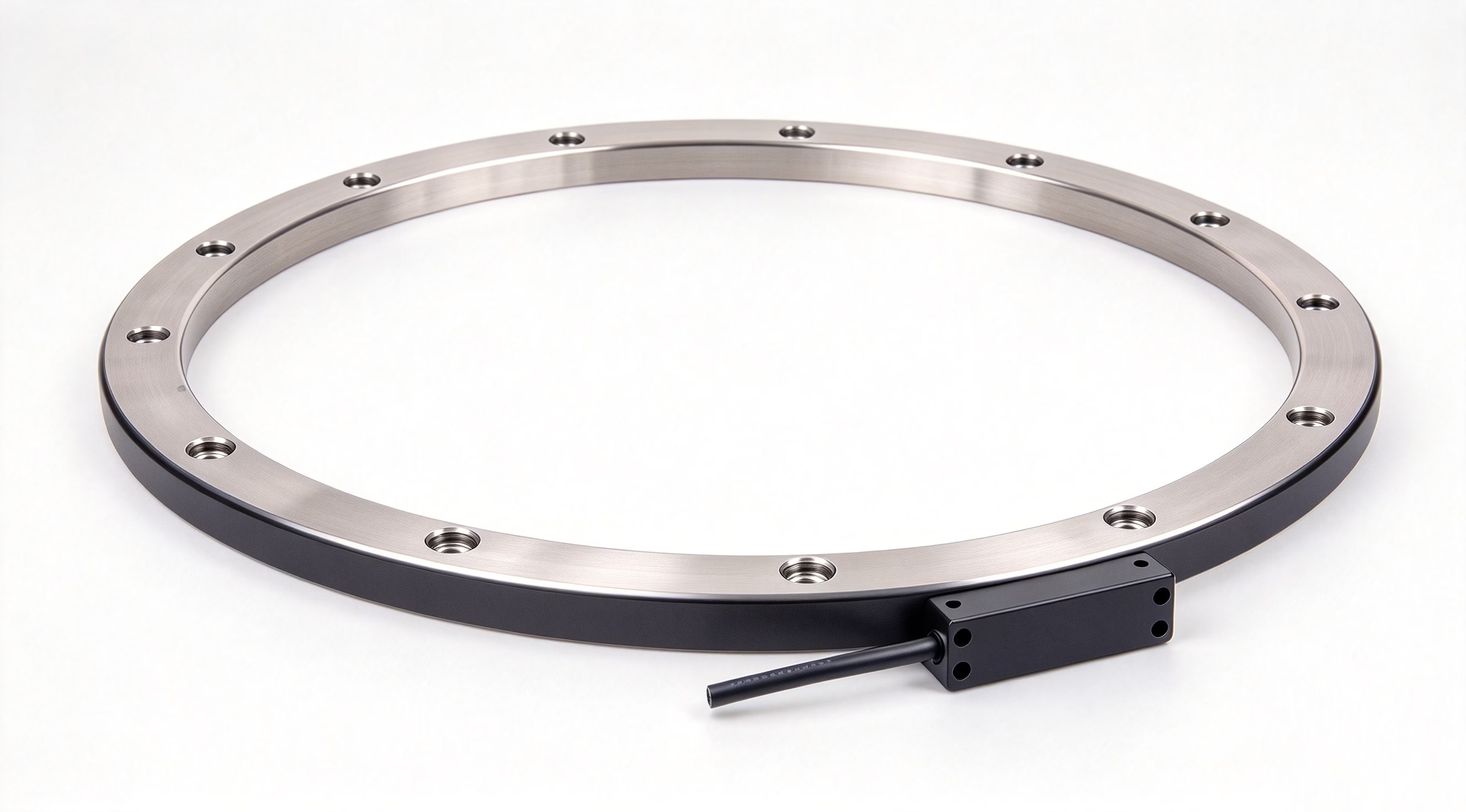 Housed industrial readhead
OMR: industrial interfaces + larger rings
Evaluate OMR when you need a housed readhead, BiSS-C or SSI over RS422, or MODBUS-RTU or Tamagawa over RS485. Its published range lists finer resolution and accuracy specifications and standard magnetic rings with larger outer diameters.
| Selection factor | OTV-OMER radial series | OMR absolute magnetic rotary encoder |
|---|---|---|
| Readhead construction | Curved open PCB; matched magnetic ring and readhead kit | Aluminium housed readhead; published housing size 53 × 14 × 12.5 mm |
| Standard ring bore / OD | 38.8–60 mm ID / 43.8–65 mm OD across four sizes | 60–285 mm ID / 81.53–325.94 mm OD across the six listed standard rings |
| Ring thickness / height | 3–4 mm ring thickness | 12–14 mm ring height in the standard-ring table |
| Resolution | 14-bit: 16,384 positions/rev, approximately 0.022° per step | Published angular resolution down to 0.1 arcsecond (approximately 0.000028°); verify the selected output configuration |
| Listed angular accuracy | Positioning accuracy: 0.396° worst / 0.374° average | Published absolute accuracy ≤0.05° |
| Output / controller connection | SPI with 3.3 V logic | BiSS-C / SSI via RS422; MODBUS-RTU / Tamagawa via RS485 |
| Supply / no-load current | 5 V ±5%; <25 mA at 25°C | 5 V ±5%; <160 mA at 25°C |
| Readhead-to-ring gap | Recommended 1.0 ±0.2 mm | Published optimal gap 0.3 ±0.1 mm; maximum ≤0.6 mm |
| Readhead protection | Customer enclosure required. The ring-only IP67 claim does not protect the PCB. | The OMR product page lists IP67 protection for its housed encoder; confirm the selected readhead, cable and installation conditions. |
| Primary selection route | Smaller ring envelope, low listed no-load current and embedded SPI integration | Industrial controller interfaces, larger standard ring sizes and tighter published accuracy requirements |
OMR figures are taken from its published product specifications. The two families use different specification terminology and test conditions; these are selection references, not a test under identical conditions. Resolution is not accuracy. Ring dimensions and readhead dimensions do not represent the complete installed envelope.
Hollow-shaft absolute encoder selection FAQ
Is OTV-OMER an axial or radial reading encoder?
It reads radially from the magnetic ring’s outer circumference. The readhead is positioned alongside that outer edge. Use the approved mounting drawing to establish its exact position and clearance.
Does a larger ring provide better resolution or accuracy?
Not within these four listed configurations. All use 14-bit SPI output and share the same catalogue accuracy and repeatability values. Choose the ring size for mechanical fit, then validate the mounted assembly.
Is this a multiturn absolute encoder?
The listed OTV-OMER configuration is single-turn absolute. Multiturn tracking, additional interfaces and higher resolution are not specified for this family here. Tell us the required function so we can assess a suitable product.
Can I use the ring with any magnetic encoder IC?
No compatibility should be assumed. The magnetic pattern, readhead sensing arrangement and installation geometry form a matched system. OTV Sensing supplies the ring and readhead together for selection and integration review.
Is the entire encoder IP67 or rated for 600 bar?
No. These catalogue claims concern the magnetic ring only. The open PCB readhead requires customer protection. Discuss the actual environment and ring test conditions before specifying pressure or ingress performance.
What should I send for a size or quotation review?
Send the required shaft opening, maximum ring OD, available radial and axial space, operating speed, accuracy target, controller interface and environment. Include quantity and target schedule. For a non-standard size, request a feasibility review before treating it as available.
Find the right matched radial encoder kit
Share your bore, mounting space and feedback requirements. OTV Sensing will review the ring and readhead together with your integration needs.
Include: ring ID / maximum OD / available height / speed / accuracy / interface / environment / quantity.