
Incremental Magnetic Linear Encoders & Readheads
Select incremental feedback for your machine’s space, speed and control requirements. Compare compact magnetic readheads, miniature heads with remote electronics, separate 5 V and 24 V models, and integrated reference/limit options.
OTV-IML pairs a non-contact readhead with a matched magnetic scale, or a compatible linear motor magnet track. Choose the mechanical envelope, electrical interface and homing functions together.

Select an Incremental Magnetic Readhead for Your Axis
Start with the space and function your axis needs. Then check resolution, speed, supply and scale compatibility in the model table.
IML200-C33 / C36
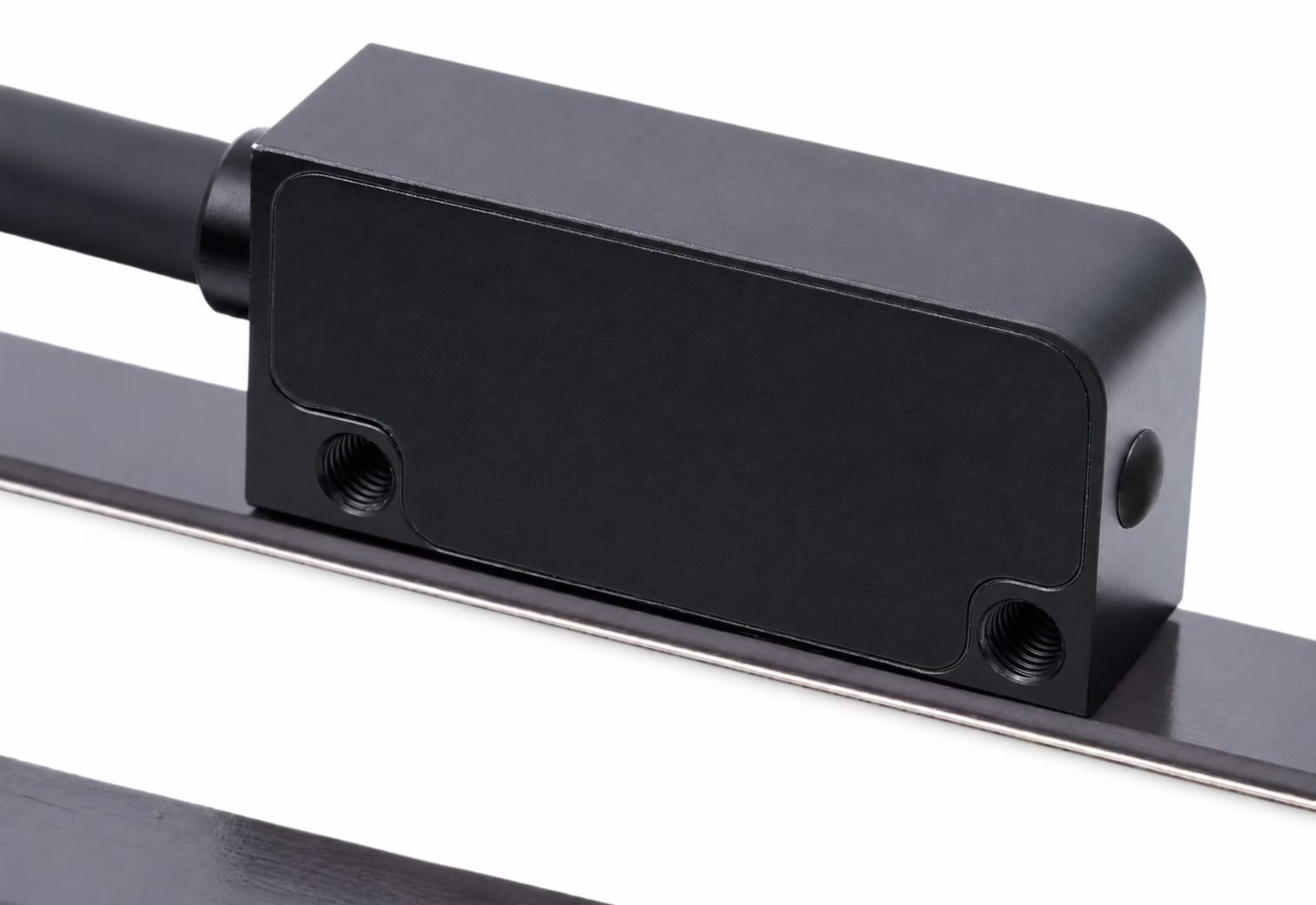
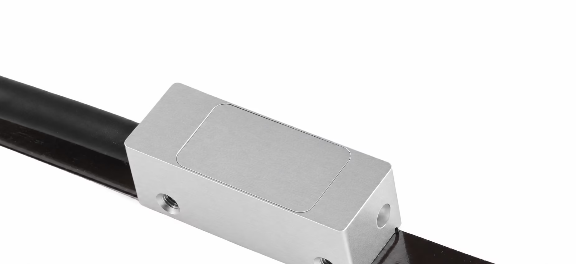
Compare 33 × 15 × 10 mm and 36 × 13.5 × 12.5 mm housings. Down to 0.5 µm resolution; periodic or unique reference configurations.
Explore this option →IML200-M / MR / MX
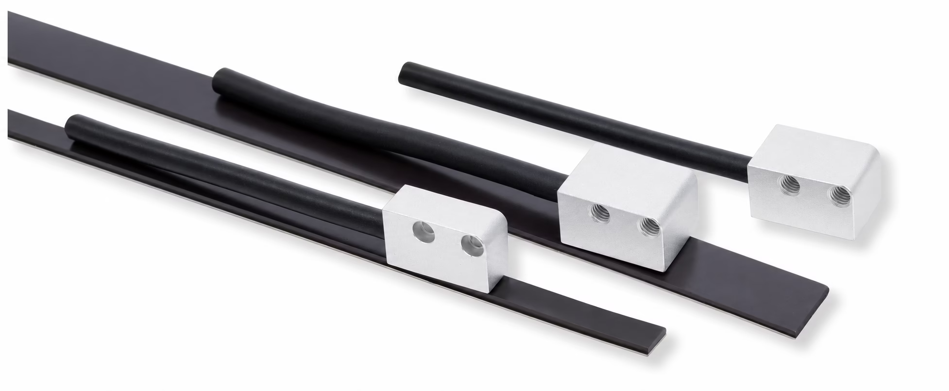
Miniature heads with processing in a DB15 connector or separate box. M: 15 × 9 × 10 mm. MX: 15 × 9 × 6 mm.
Explore this option →IML200-HS
11 m/s at 0.5 µm resolution, with a choice of mounting profiles for different axis layouts.
Explore this option →IML500-5V / 24V
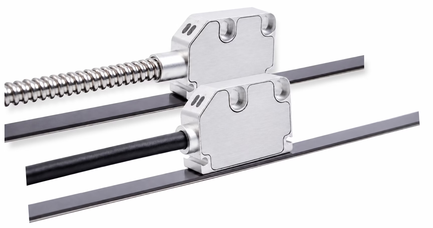
Separate 5 V / 24 V supply models. Up to 2 mm mounting gap (1.5 mm recommended). RS422 / TTL, single-ended / differential digital, or Sin/Cos analog output options.
Explore this option →IML200-R32 / L
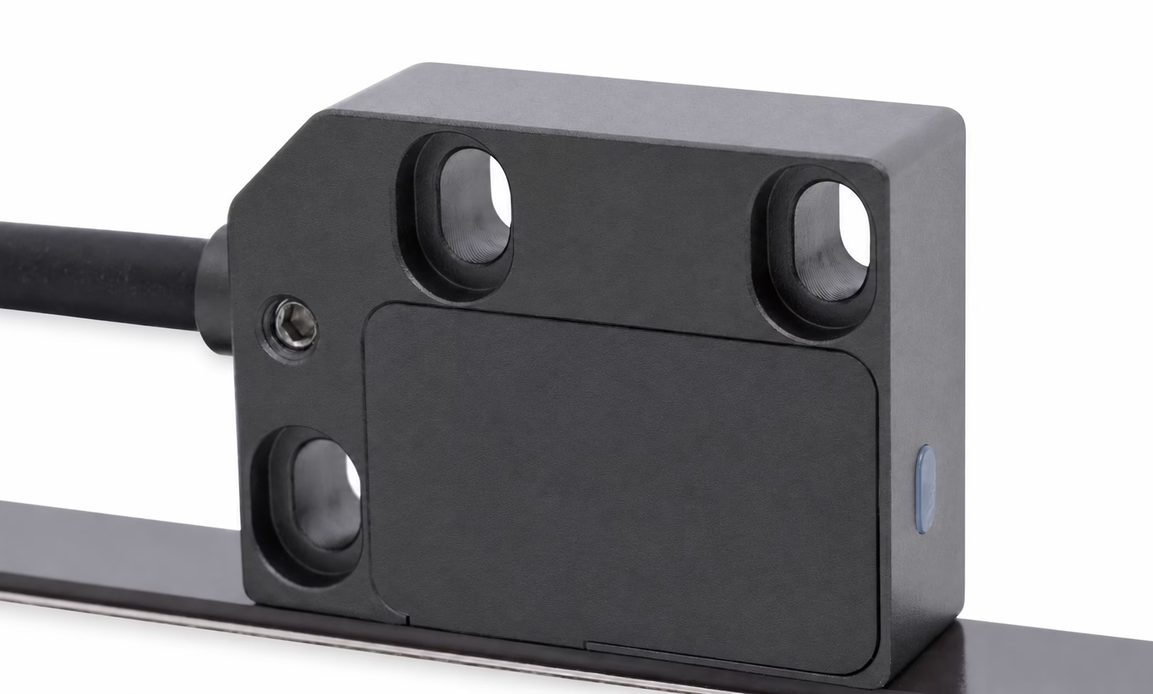
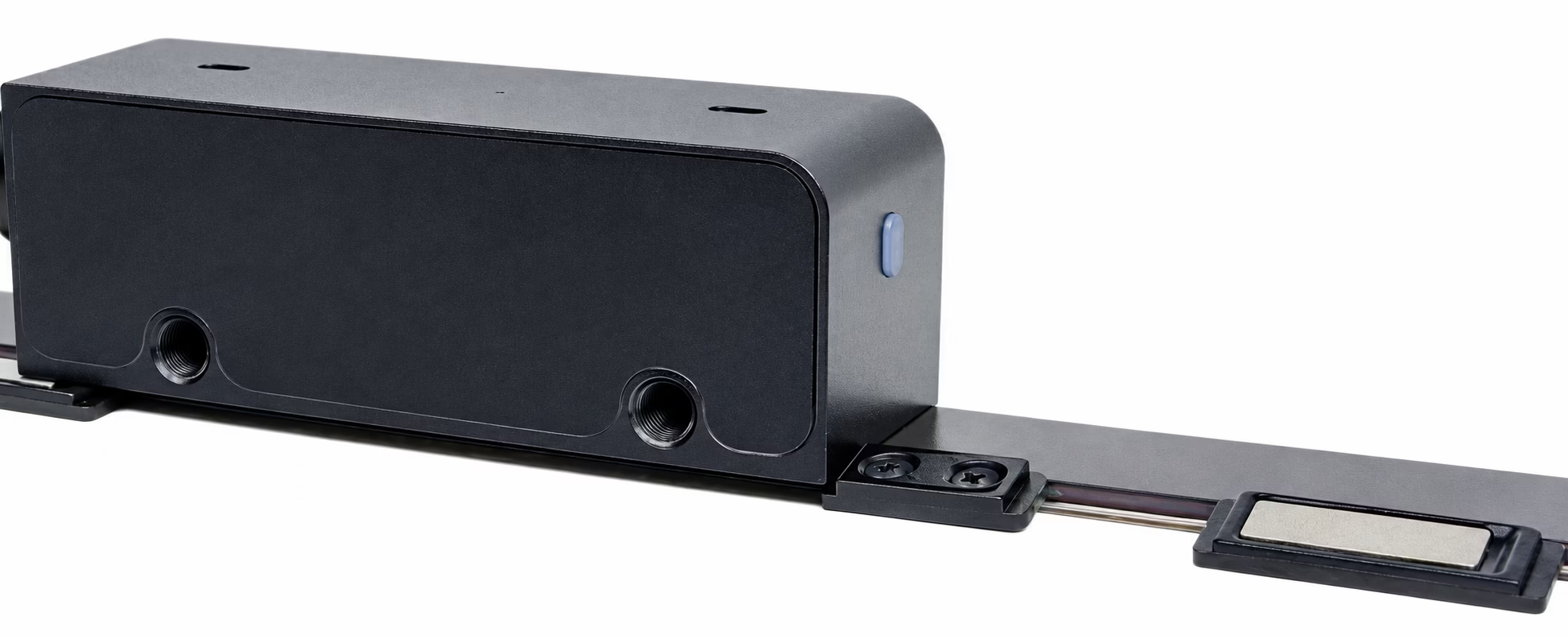
R32 provides a unique reference. L combines incremental feedback, a unique reference and left/right limit outputs.
Explore this option →IML-MC / IML200-PCB
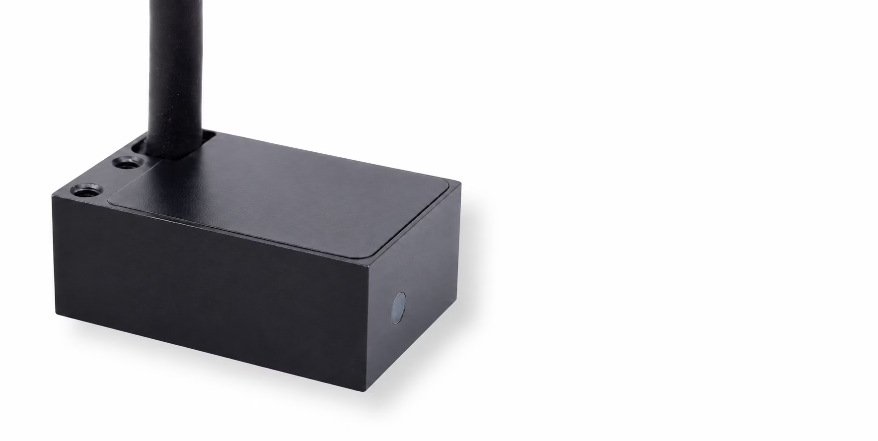
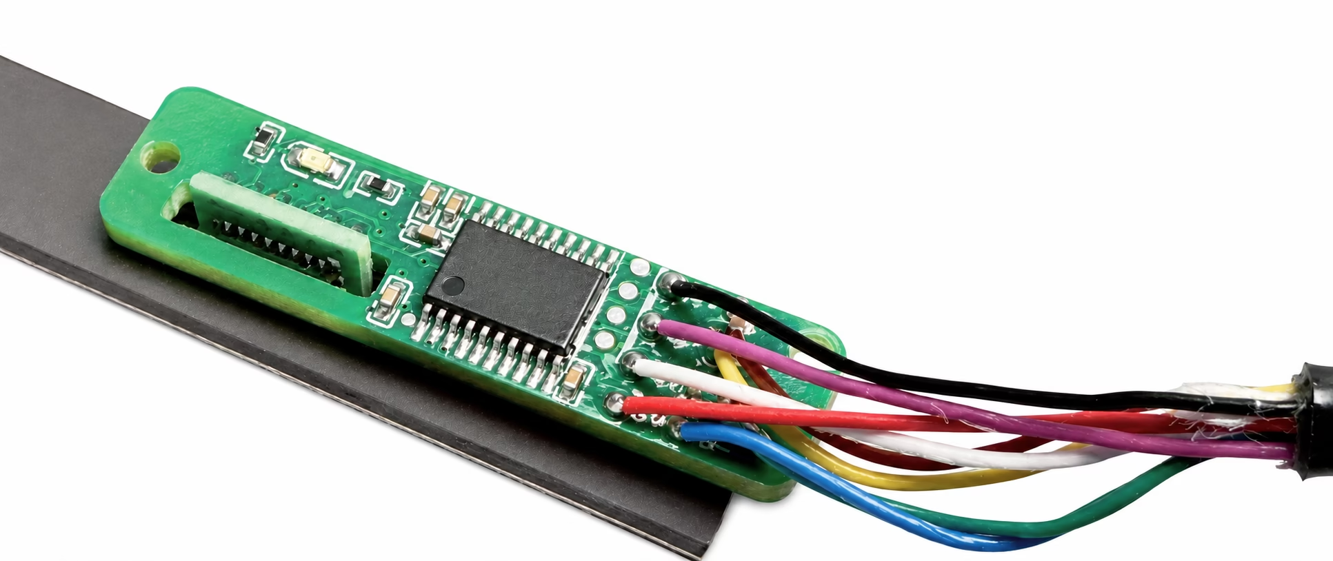
MC reads a matched motor magnet track with UVW commutation. PCB fits OEM electronics and mechanical designs.
Explore this option →Product images and mounting drawings are details from the supplied catalogue. High-speed profiles are shown as drawings where no separate photograph is available. Open an image to view the detail.
Compare OTV-IML Incremental Linear Encoder Models
IML identifies Incremental Magnetic Linear feedback. The 200 and 500 tape-based groups use different matched scale families; MC identifies the motor-magnet architecture. Order the readhead, scale and signal configuration as a matched system.
Use the numbered icons and colors to match each row to the six selection groups above. Scroll the comparison horizontally on smaller screens. Readhead envelopes and mounting drawings are shown in the dimensions section below.
| Family / model | Supply | Resolution | Positioning accuracy | Max. measurement length | Max. speed | Digital output / interface | Body / gap / protection | Reference / integration |
|---|---|---|---|---|---|---|---|---|
| 01 · Compact axesIML200-C33Compact axes; periodic or unique reference | 5 V | Down to 0.5 µm | ≤40 µm (1 m test)Catalogue 1 m interferometer test, 0.5 mm gap. | 50 m* | 8 m/s at 0.5 µm | RS422 differential A/B/Z | 33 × 15 × 10 mmGap: <1 mmIP67 | Periodic or unique reference configuration |
| 01 · Compact axesIML200-C36Alternative housing and mounting geometry | 5 V | Down to 0.5 µm | ≤40 µm (1 m test)Catalogue 1 m interferometer test, 0.5 mm gap. | 50 m* | 8 m/s at 0.5 µm | RS422 differential A/B/Z | 36 × 13.5 × 12.5 mmGap: <1 mmIP67 | Periodic or unique reference configuration |
| 03 · High speedIML200-HSHigh-speed axes and alternative mounting profiles | 5 V | Down to 0.5 µm | ≤50 µm (1 m test)Catalogue 1 m interferometer test, 0.2 mm gap. | 50 m* | 11 m/s at 0.5 µm | RS422 differential A/B/Z | Gap: <1 mmIP67 | Reference configuration selected with the scale |
| 02 · MiniatureIML200-MSmall readhead with electronics in DB15 or separate box | 5 V | 0.5 / 1 µm | <30 µmCatalogue positioning accuracy; do not extrapolate to maximum travel. | 50 m* | Up to 5 m/s, configuration-dependent | TTL differential quadrature; A/B/Z wiring options | 15 × 9 × 10 mmGap: <1 mm; recommended 0.5 ±0.1 mmIP67 sensor | Reference configuration selected with the scale |
| 02 · MiniatureIML200-MRMiniature unique-reference layout | 5 V | 0.5 / 1 µm | <30 µmCatalogue positioning accuracy; do not extrapolate to maximum travel. | 50 m* | Up to 5 m/s, configuration-dependent | TTL differential quadrature; unique-reference option | Gap: <1 mm; recommended 0.5 ±0.1 mmIP67 sensor | Unique reference, with matched scale |
| 02 · MiniatureIML200-MXThin miniature profile | 5 V | 0.5 / 1 µm | <30 µmCatalogue positioning accuracy; do not extrapolate to maximum travel. | 50 m* | Up to 5 m/s, configuration-dependent | TTL differential quadrature; A/B/Z wiring options | 15 × 9 × 6 mm drawing envelopeGap: <1 mm; recommended 0.5 ±0.1 mmIP67 sensor | Reference configuration selected with the scale |
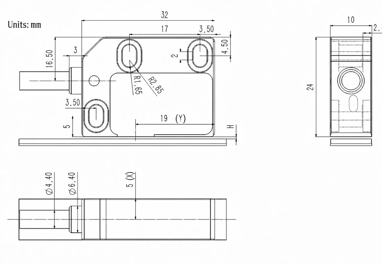
| 05 · Reference & limitsIML200-R32Unique reference in a 32 mm housing | 5 V | Down to 0.5 µm | ≤50 µmCatalogue positioning accuracy; do not extrapolate to maximum travel. | 50 m* | 8 m/s at 0.5 µm | RS422 differential A/B/Z | 32 × 24 × 10 mmGap: <1 mmIP67 | Unique reference, with matched scale |
| 04 · Supply & clearanceIML500-5V5 V supply; larger mounting clearance | 5 V | Digital output: 2.5–625 µm selectable | <30 µmCatalogue positioning accuracy; do not extrapolate to maximum travel. | 50 / 100 m catalogue configurations* | Up to 9 m/s, configuration-dependent | RS422 / TTL digital; single-ended or differential output; Sin/Cos analog (by configuration) | 35 × 25 × 10 mmGap: Up to 2 mm; recommended 1.5 mmIP67 sensor | Reference configuration selected with the scale |
| 04 · Supply & clearanceIML500-24V24 V supply; separate model identity | 24 V | Digital output: 2.5–625 µm selectable | <30 µmCatalogue positioning accuracy; do not extrapolate to maximum travel. | 50 / 100 m catalogue configurations* | Up to 9 m/s, configuration-dependent | RS422 / TTL digital; single-ended or differential output; Sin/Cos analog (by configuration) | 35 × 25 × 10 mmGap: Up to 2 mm; recommended 1.5 mmIP67 sensor | Reference configuration selected with the scale |
| 05 · Reference & limitsIML200-LUnique reference and left/right limit outputs in one head | 5 V encoder supply | 1 µm | <60 µmCatalogue positioning accuracy; do not extrapolate to maximum travel. | 50 m* | Up to 5 m/s, configuration-dependent | RS422 / TTL differential A/B/Z; open-collector reference/limit I/O | 44 × 15 × 15 mmGap: 0.2–0.3 mm | Unique reference + left/right limits |
| IML-MCRead a matched motor magnet track, with UVW commutation | 5 V | 1 µm | <300 µmCatalogue positioning accuracy; do not extrapolate to maximum travel. | 50 m* | Up to 5 m/s, configuration-dependent | RS422 incremental A/B + single-ended UVW | 31 × 20 × 12 mmGap: 2 mm, excluding protective coverIP67 sensor | Incremental feedback and UVW commutation |
| IML200-PCBBoard-level incremental feedback for embedded designs | 5 V | 1 / 2 / 10 µm | — | — | Up to 5 m/s, configuration-dependent | TTL / RS422 incremental A/B/Z | — | Unique reference configuration |
* Catalogue maximum measurement length depends on the matched magnetic scale or compatible motor track. It is not cable length and does not establish accuracy over the complete travel. The IML500 source lists 50 m / 100 m configurations without assigning each length to a supply version. Select travel and output wiring with the matched configuration. IP67 applies only where specified for the model or sensor.
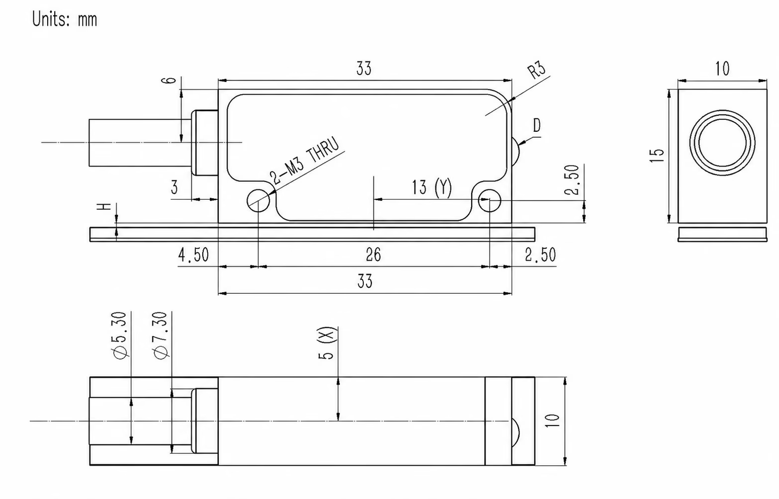
Readhead Dimensions and Mounting Space
Compare the readhead envelope before selecting the mounting arrangement. All dimensions shown are in millimeters. Open the drawing for a larger view, and use the selected configuration drawing for the assembly.
IML200-C33
26 mm mounting-hole spacing.
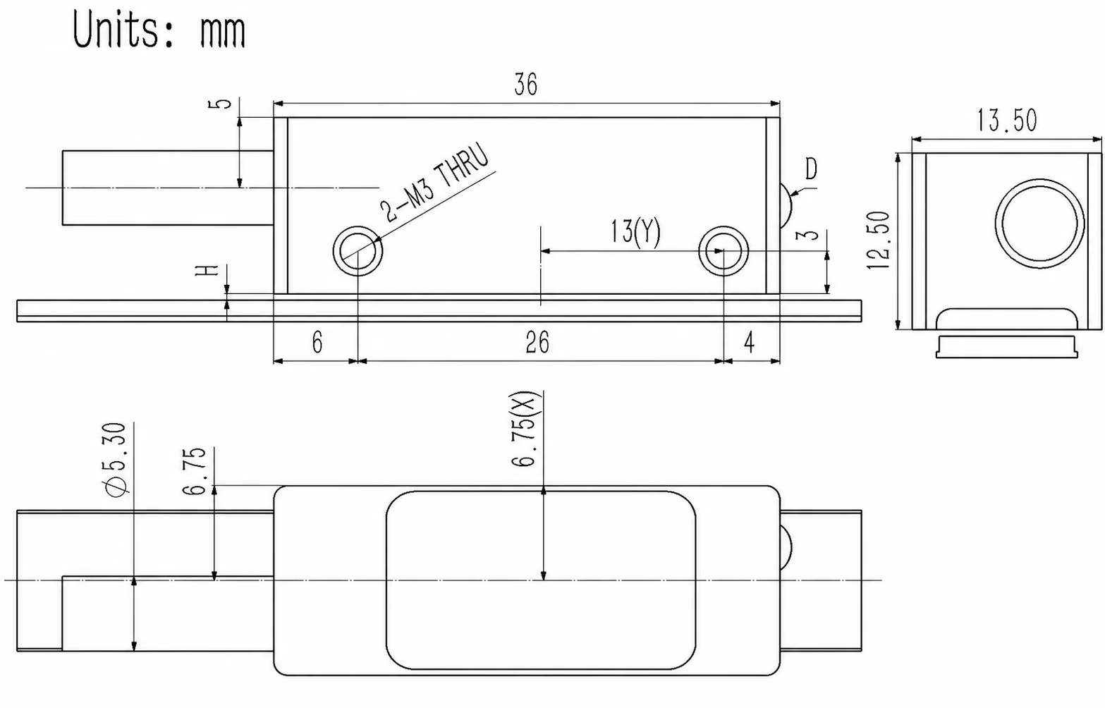
IML200-C36
26 mm mounting-hole spacing.
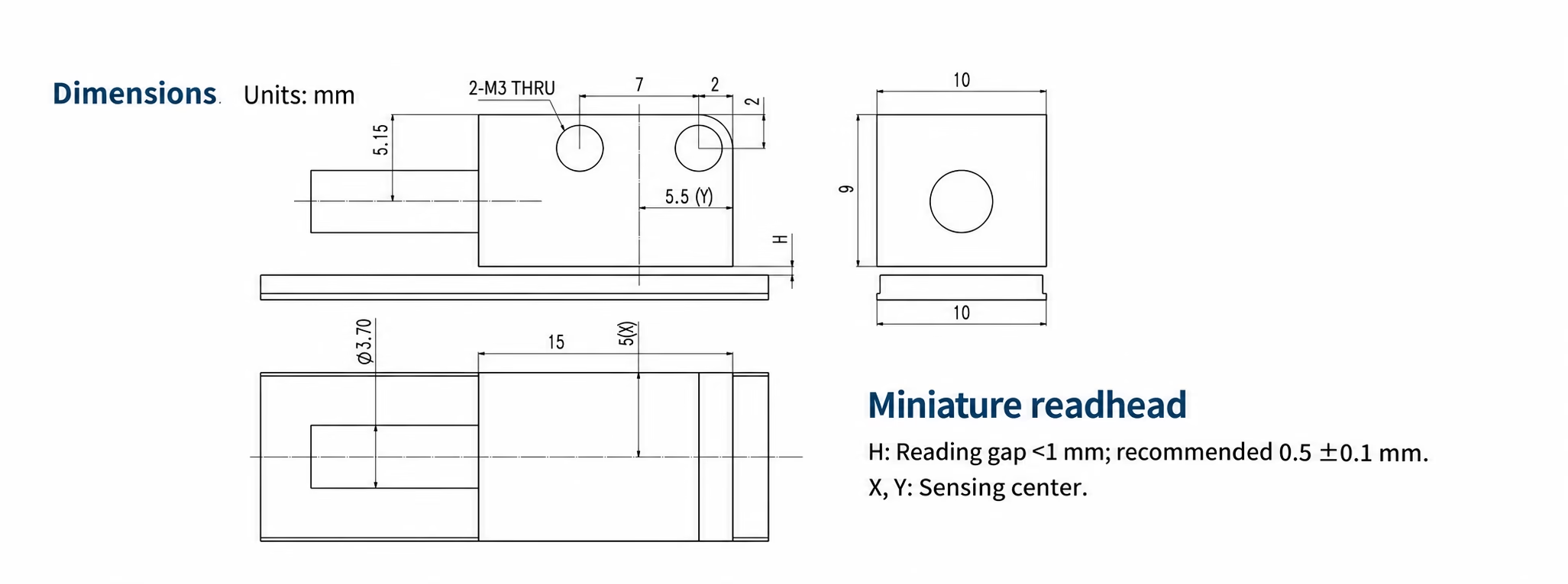
IML200-M
7 mm mounting-hole spacing; remote electronics layout.
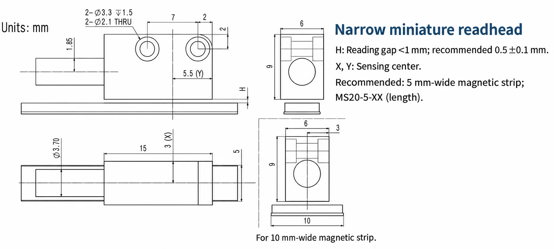
IML200-MX
Source drawing shows mounting arrangements for the magnetic strip.
IML200-HS
Alternative mounting profiles use their corresponding mechanical drawing.
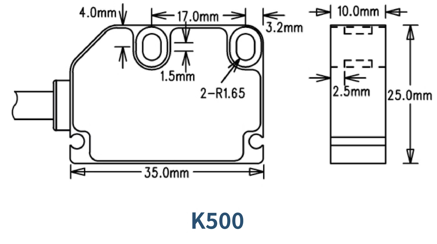
IML500-5V / 24V
17 mm mounting-hole spacing; supply versions share this housing.
IML200-R32
17 mm mounting-hole spacing.
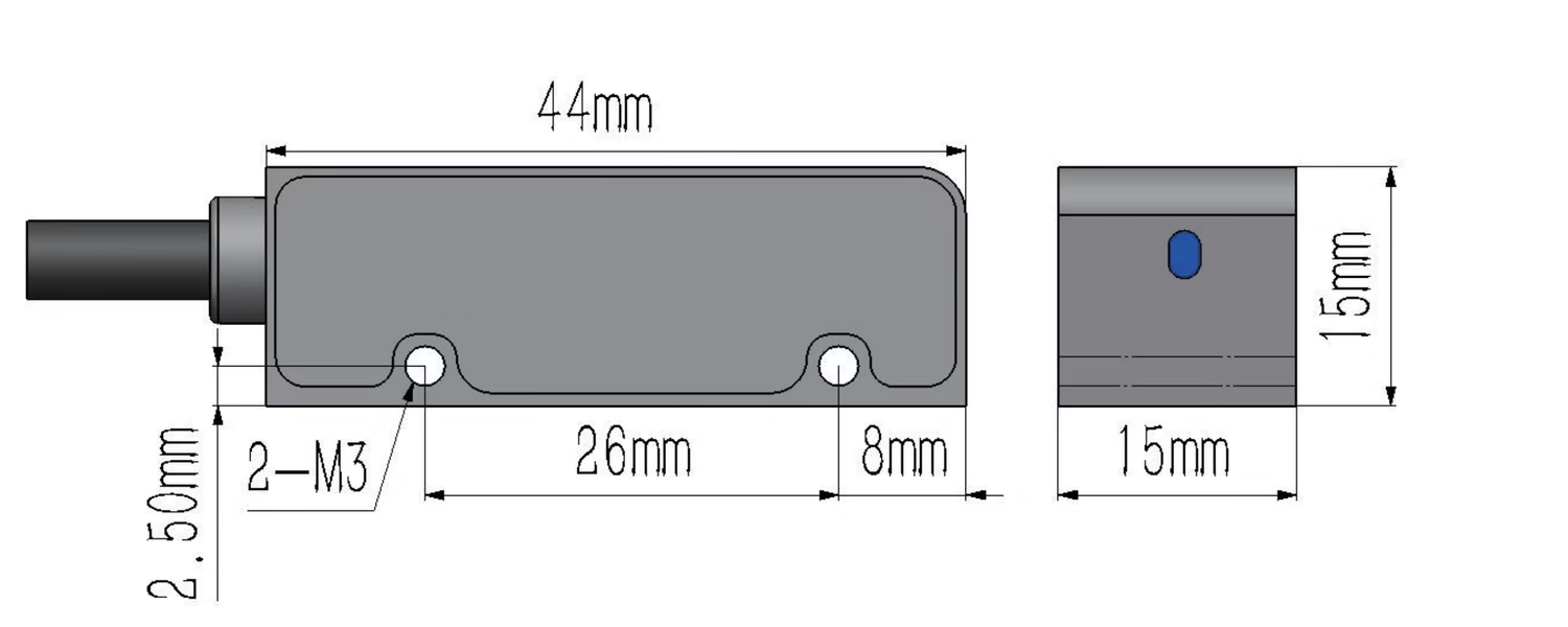
IML200-L
26 mm mounting-hole spacing; reference and limit sensing.
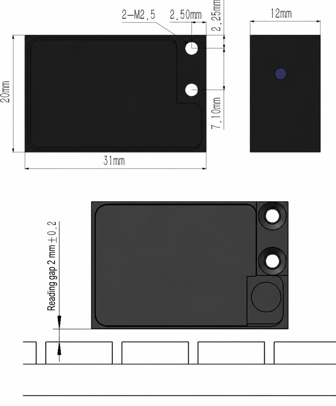
IML-MC
Sensing gap is specified separately from the body envelope.
IML200-PCB
PCB mounting and sensing arrangement as shown in the source drawing.
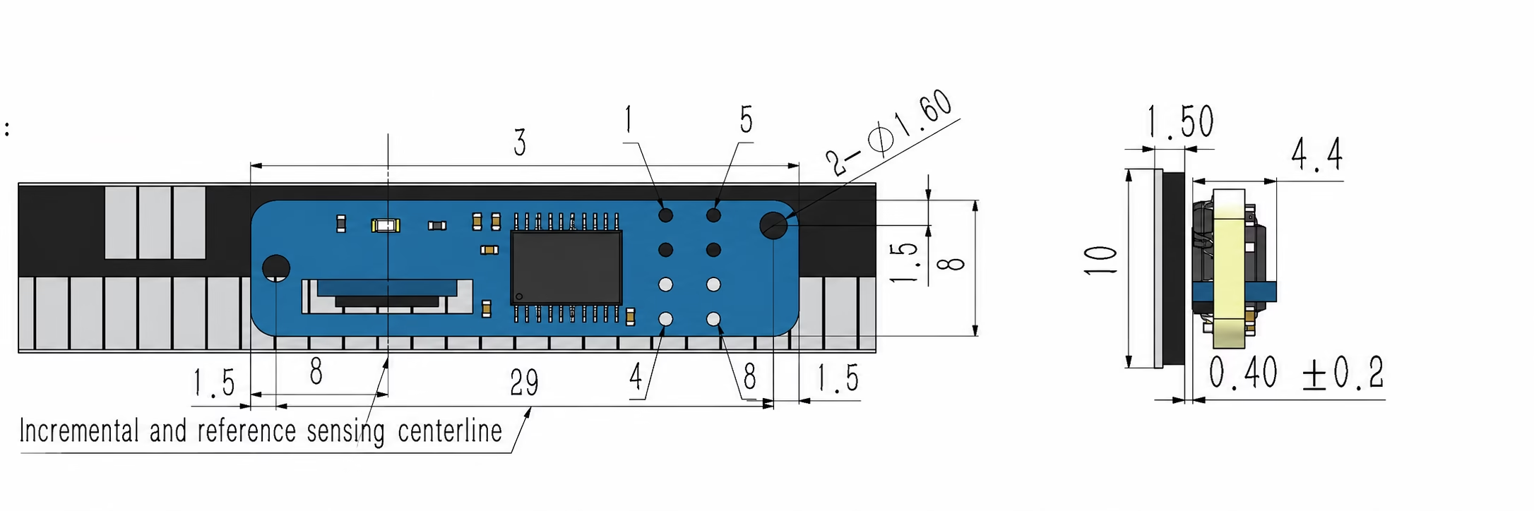
Body dimensions, sensing gap and remote electronics space are separate mechanical requirements. The drawing for the ordered mounting profile governs the installation.
Miniature Incremental Readheads with Remote Electronics
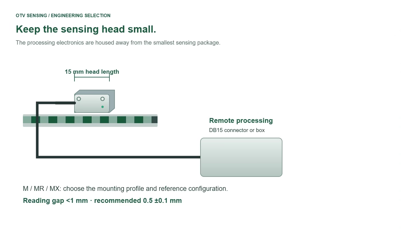
When a connector or processing circuit will not fit on the moving axis, move the electronics away from the sensing head. The IML200-M, MR and MX options suit compact stages and embedded motion assemblies where cable routing and head height matter.
- IML200-M: 15 × 9 × 10 mm readhead.
- IML200-MX: 15 × 9 × 6 mm readhead for a narrower profile.
- IML200-MR: miniature unique-reference configuration with a matched scale.
- Installation gap: <1 mm; recommended 0.5 ±0.1 mm.
Choose processing in a DB15 connector or a separate box. Confirm the complete head-to-electronics and electronics-to-controller cable arrangement with your drawing.
View the system architecture illustration
5 V and 24 V Encoders: Digital and Sin/Cos Output Options
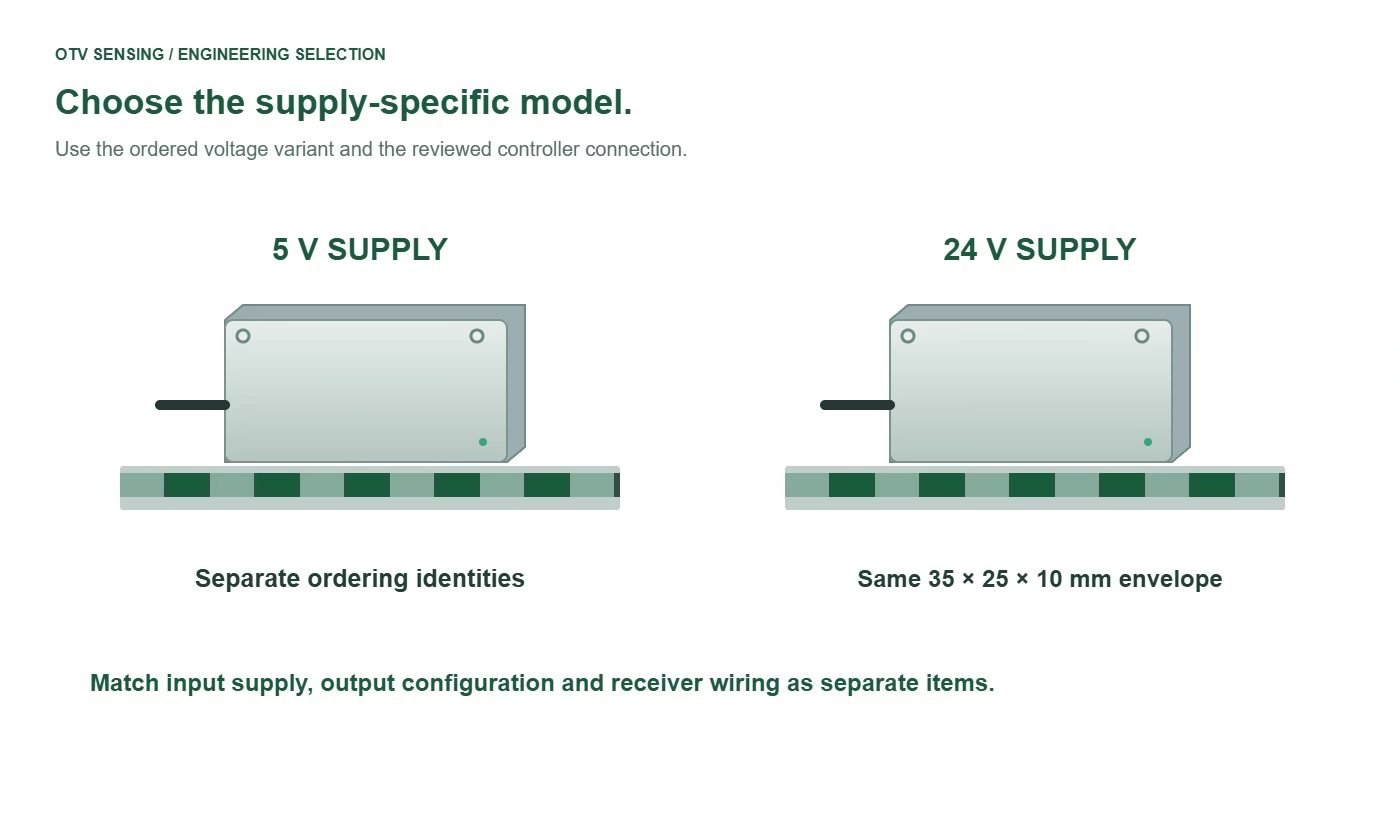
IML500-5V and IML500-24V are separate models for 5 V and 24 V input supply. Both use a 35 × 25 × 10 mm housing and a matched 5 mm magnetic scale.
Select resolution from 2.5–625 µm, with a mounting gap up to 2 mm and recommended gap of 1.5 mm. Maximum speed is up to 9 m/s on the applicable configuration.
Specify supply and signal separately. The 5 V / 24 V designation describes input power. Specify the digital interface and wiring arrangement, or the Sin/Cos analog option, and confirm compatibility with the receiving input.
For 5 V compact heads with finer output increments, compare the IML200 models above.
View the system architecture illustration
Incremental Feedback with Unique Reference and Limit Outputs
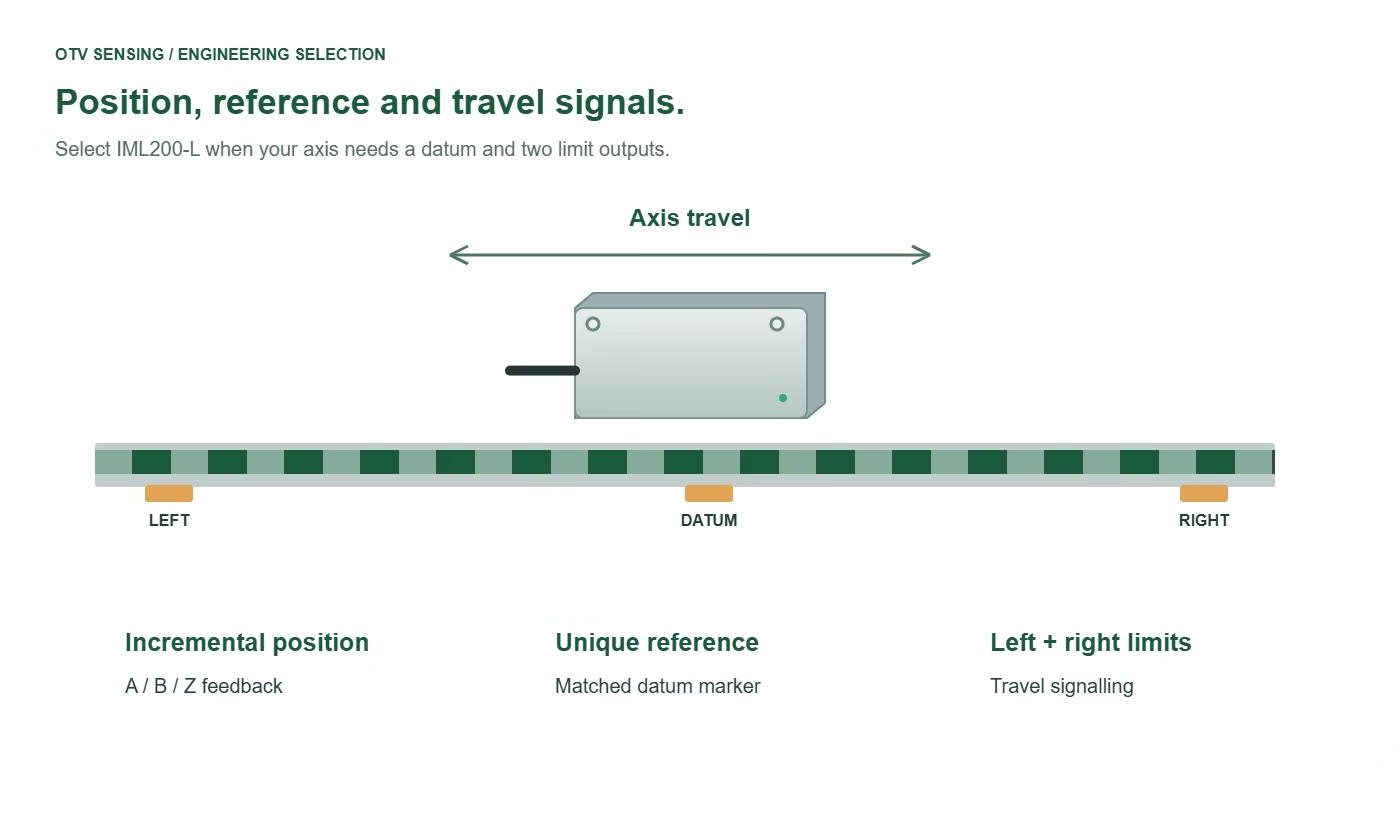
IML200-L combines incremental feedback, one unique reference and left/right limit outputs in a 44 × 15 × 15 mm head. It is an option for axes that need a repeatable datum and end-of-travel signals in the same sensing arrangement.
The head uses a 5 V encoder supply, 1 µm resolution and a 0.2–0.3 mm installation gap. Configure the matched scale and markers to suit the usable travel.
The reference/limit I/O uses a separate 5–24 V supply and open-collector outputs. Review wiring and input compatibility with OTV Sensing. Travel limit signals are for machine control; they are not a safety-rated function.
If you need a unique reference without two integrated limits, compare IML200-R32 or IML200-MR.
View the system architecture illustration
Linear Motor Magnet Track Feedback with UVW Commutation
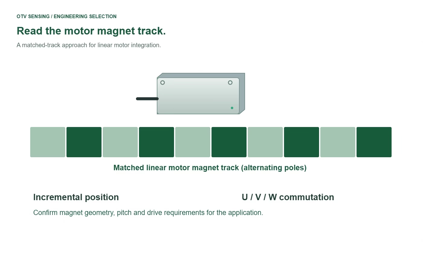
IML-MC reads a compatible linear motor stator magnet track and provides incremental position feedback plus UVW commutation signals. In this matched architecture, the motor magnets form the sensing track, removing the need for a separate encoder tape.
The 31 × 20 × 12 mm sensor offers 1 µm resolution, a 5 V supply and up to 5 m/s on the applicable configuration. Catalogue motor-track pitch options are 20, 24, 30, 32 and 36 mm. The stated sensing gap is 2 mm, excluding a protective cover.
Send your motor magnet drawing for evaluation. Track compatibility, magnet geometry and the required axis accuracy must be checked together. This is incremental feedback and requires a suitable machine referencing strategy.
View the system architecture illustration
PCB-Level Incremental Encoder Readheads for Embedded Motion Systems
IML200-PCB is the board-level choice for equipment builders integrating the sensor into their own enclosure or mechanism. Pair it with a matched 2 mm magnetic scale and unique-reference configuration.
Choose 1, 2 or 10 µm resolution and the selected digital TTL/RS422 interface. The encoder uses a 5 V supply, with speed up to 5 m/s on the applicable configuration.
OTV Sensing can configure cable length and connectors for the installation. Share the available space, cable exit direction and controller interface so the board, reference marker and protection arrangement can be reviewed together.
Matched Magnetic Scales: Width, Thickness and Reference Marks
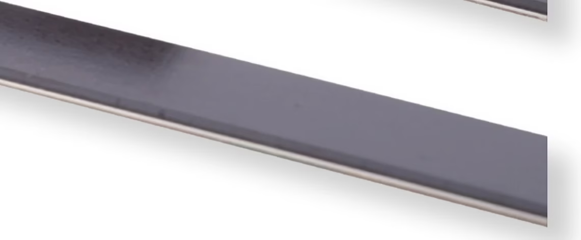
The magnetic strip is part of the sensing system. Select the scale family, width and reference pattern for the chosen readhead and mounting geometry.
MS20 / MSR20 matched scales for IML200
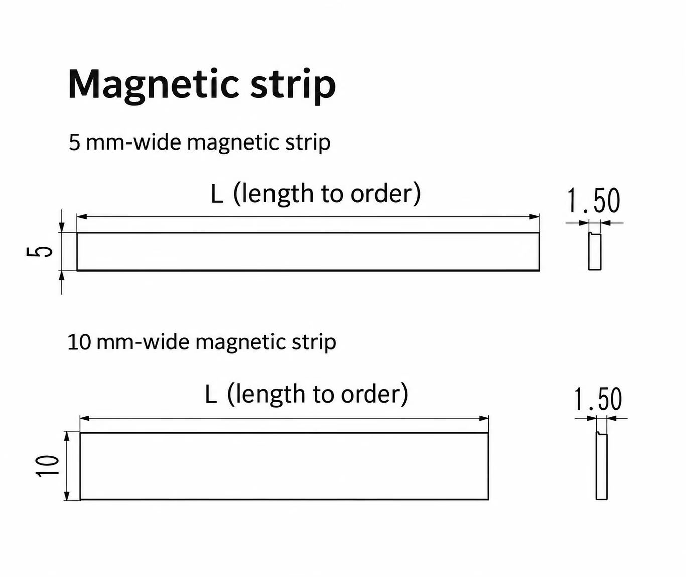
The supplied MS20-family drawings show two strip widths and a 1.5 mm thickness. The readhead and mounting arrangement determine the selected width and sensing alignment.
- Scale family: matched 2 mm catalogue pitch configuration.
- Reference pattern: select the required scale/marker arrangement for periodic or unique-reference operation.
- Miniature integration: the MX source drawing recommends a 5 mm strip for its narrow arrangement.
- Assembly space: check the selected adhesive, protective cover and support arrangement against the installation drawing.
MS50 for IML500-5V / 24V
IML500 uses the matched 5 mm catalogue scale family. Choose the tape and reference configuration with the readhead; MS20 mechanical dimensions are not a specification for MS50.
Unique reference and limit markers
The required reference or travel-limit behavior depends on the selected readhead and marker arrangement. Send the usable travel and datum/limit positions with your drawing.
IML-MC motor magnet track
IML-MC reads a compatible motor stator magnet track. This matched architecture uses the motor magnets in place of a separate encoder tape.
Encoder Cables, Connectors and Drag-Chain Routing
Select the cable with the readhead, output wiring and machine routing. Lead length, connector pinout and the position of any remote electronics form part of the ordered configuration.
Cable lengths and termination options
| Readhead / group | Catalogue lead lengths or layout | Termination / cable options |
|---|---|---|
| IML200-C33 / C36 / HS / R32 | 0.5 m standard lead in the supplied specification tables; custom lengths can be specified. | Flying leads (NC), DB9 or DB15 connection, selected with the readhead configuration. |
| IML200-M / MR / MX | Separate-box ordering examples: N0.5 / M0.5, N0.5 / M3 and N3 / M10, in meters. Specify each leg separately. | Electronics in a DB15 connector or separate processing box. The connector-electronics arrangement uses the N lead. |
| IML500-5V / IML500-24V | Listed lead-length examples include 0.5, 1, 1.5, 3 and 10 m. Specify the required length in the order. | Rubber-jacket or metal-conduit cable option; flying leads, DB9 or selected DB15 connection. |
| IML200-L | 3 m lead in the specification table; custom length available. | Flying leads or selected DB15 connection; include the reference/limit I/O wiring requirements. |
| IML-MC | 3 m lead in the specification table; custom length available. | Flying leads or selected DB15 connection; use the motor-track model’s signal assignment. |
| IML200-PCB | Bare-board or cabled configuration. Listed lead examples include 0.3, 1 and 1.5 m. | Flying leads, DB9 or selected DB15 option on the cabled assembly. |
DB15 arrangements and pin assignments vary by product. Select the connector and wiring diagram with the exact readhead; a matching connector shell alone does not establish electrical compatibility.
IML200-R32 high-flex cable specification
The following figures describe the 8-core cable listed for the R32 catalogue configuration.
| Characteristic | R32 cable configuration |
|---|---|
| Cable construction | High-flex, drag-chain compatible, dual-shielded twisted-pair cable |
| Jacket material | TPU |
| Conductor count | 8 |
| Outside diameter | 5.3 ±0.15 mm |
| Shielding coverage | >98% |
| Internal bend radius | 25 mm dynamic / 10 mm static |
| Listed flex endurance | 30 million cycles at a 37 mm bend radius |
| Nominal cable mass | 34 g/m |
The endurance figure is tied to the stated 37 mm test radius. The 25 mm dynamic bend-radius value is a separate specification.
Specify the cable with your axis
Readhead → N lead → processing box → M lead → controller
- Length and routing: state the required head-to-controller length; for a separate processing box, provide N and M separately.
- Motion: identify fixed or moving installation, the cable-carrier path and the available bend radius.
- Electrical connection: provide the selected output interface, receiving input, connector type and pin assignment.
- Assembly: include the cable exit direction, shielding connection requirements and any conduit preference in the drawing.
Cable length and axis travel are separate specifications. The C33/C36/HS/R32 data list a 30 m maximum cable figure with a laboratory voltage-drop condition of 4.75 V. Review the required cable length with the selected supply and receiving input for the actual installation.
Match the Magnetic Readhead, Scale and Controller
Space & scale
Specify travel, head envelope, gap, mounting faces, cable route and operating temperature. Match the scale family to the head; similar-looking magnetic tapes are not automatically interchangeable.
Explore magnetic encoder tapes →Resolution & speed
State the required resolution and axis accuracy separately. Give maximum speed and the controller’s quadrature input specification so output rate and input compatibility can be checked.
Signals & homing
Specify supply, digital interface, reference behavior and any travel-limit outputs. Most housed tape-based options use differential incremental signals; the MC and L architectures need their own wiring review.
Need position immediately after power-up? Compare our absolute magnetic linear encoder range. For compact absolute feedback, see AL228. Incremental reference markers provide a datum after referencing; they do not make an incremental encoder absolute.
Incremental Magnetic Linear Encoder FAQs
Which OTV-IML model fits the smallest installation space?
Start with IML200-M at 15 × 9 × 10 mm or IML200-MX at 15 × 9 × 6 mm. Their processing electronics are located in a DB15 connector or separate box. Include this remote electronics space and the cable route when checking your envelope.
Is there a 24 V incremental magnetic linear encoder?
Yes. IML500-24V is the 24 V input-supply model; IML500-5V is the separately named 5 V version. Both use a matched 5 mm magnetic scale. Supply voltage and signal output specification must be checked separately.
Can one readhead provide a reference and both travel limits?
IML200-L combines incremental position feedback, a unique reference and left/right limit outputs with matched scale markers. Its encoder supply is 5 V; reference/limit I/O uses a separate 5–24 V supply with open-collector outputs. Check the wiring against the selected controller.
Can the encoder read linear motor magnets directly?
IML-MC can read a matched linear motor magnet track and output incremental feedback plus UVW commutation. Send the motor magnet drawing for evaluation. Track compatibility and the application’s accuracy requirement determine suitability.
Can I order samples or a custom cable and connector?
Yes. Small sample orders typically take about one week, and regular orders about two weeks after configuration and order confirmation. Cable length and connectors can be configured. Final availability and shipping time are confirmed in the quotation.
What is the difference between incremental and absolute feedback?
An incremental system reports movement through output pulses and uses a reference strategy to establish its datum. An absolute system reports an encoded position after power-up. Choose according to the machine’s startup, homing and position-recovery requirements.
Request an OTV-IML Encoder Configuration
Send your travel, available space or drawing, required resolution and axis accuracy, maximum speed, supply, controller input, reference/limit needs and operating temperature. Include sample quantity and expected annual demand.
OTV Sensing will help select the readhead, scale or motor track, cable and connector as one configuration.
Typical lead times after configuration and order confirmation: small samples approximately 1 week; regular orders approximately 2 weeks. Shipping time is confirmed separately.