
NSM3502 & NSM350x Off-Axis Encoders
Understand the dual-track vernier principle, the challenges of compact off-axis sensing, and how to match the magnetic ring to your encoder IC. Explore applications in hollow-shaft robot joints, servo motors and rotary stages.
NSM3502 is part of the NOVOSENSE NSM350x off-axis magnetic encoder family. This guide uses NSM3502 diagrams and hardware as examples; the magnetic target, electrical requirements and IC configuration must be checked for the exact family member and released variant.
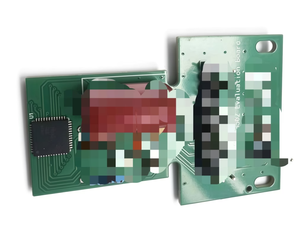
OTV Sensing support: chips, matched rings and evaluation
OTV Sensing helps coordinate chip supply, magnetic ring matching and evaluation hardware for your selected NSM3502 or NSM350x application. Tell us the exact IC variant and project stage so the magnetic target and supply request can be reviewed together.
NSM3502 IC supply
Share the exact NOVOSENSE part number, quantity and required pack format. Sample quantities and partial-pack options can be reviewed where available.
Explore encoder IC supply →Matched dual-track rings
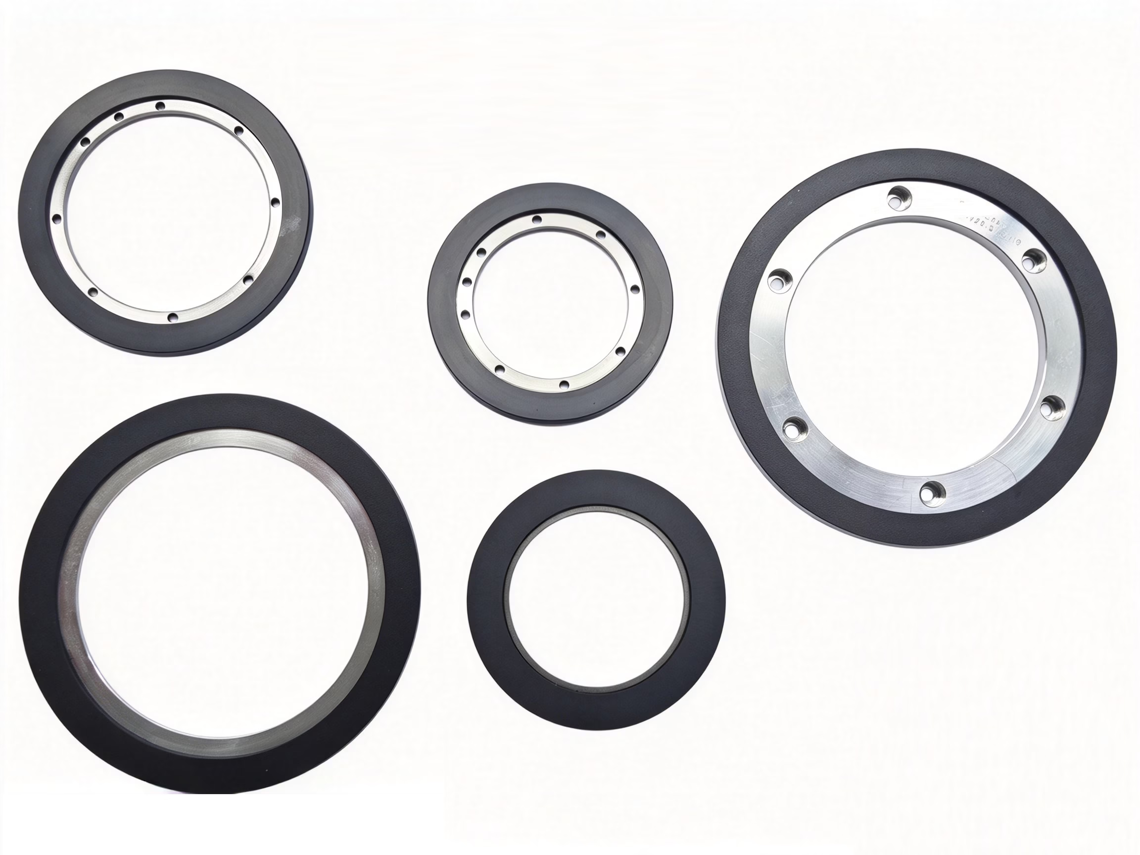
Review the bore, outside diameter, thickness and magnetic pattern together with the sensor position and gap.
Explore magnetic rings and discs →NSM3502 evaluation board
Use the board for electrical and interface evaluation while developing the ring and mechanical arrangement.
View the board and specification →OTV Sensing service flexibility: sample quantities and small-batch supply can support early evaluation and pilot builds. For production planning, share the expected annual demand and schedule. Availability, pack format, pricing and delivery are confirmed in the quotation.
How does the NSM3502 off-axis encoder work?
An off-axis magnetic encoder places the sensing IC beside the rotation axis and reads a magnetic ring attached to the rotating assembly. This layout preserves the central bore for wiring and other mechanical functions, which is useful in hollow-shaft robot joints.
Two tracks encode rotation
The Master and Nonius tracks provide related, repeating magnetic patterns. Each track generates a periodic signal as the ring rotates. Their relative phases provide the information used by the vernier calculation to identify single-turn position.
Hall arrays capture the field
The Hall sensing arrays convert the local magnetic field into electrical signals. Amplification and analog-to-digital conversion prepare the two track signals for digital processing.
The chip resolves the angle
The digital processing chain calculates angle, applies the configured calibration and produces the selected outputs. Both track patterns and the IC setup must agree for valid position decoding.
From magnetic field to angle output
The manufacturer’s functional diagram shows the Master/Nonius Hall array, amplifiers, ADCs and DSP blocks for angle calculation, calibration and interpolation. The interview also discusses CORDIC-based angle calculation as part of the signal-processing challenge. Use the released NSM3502 documentation to confirm the selected configuration and interface behavior.
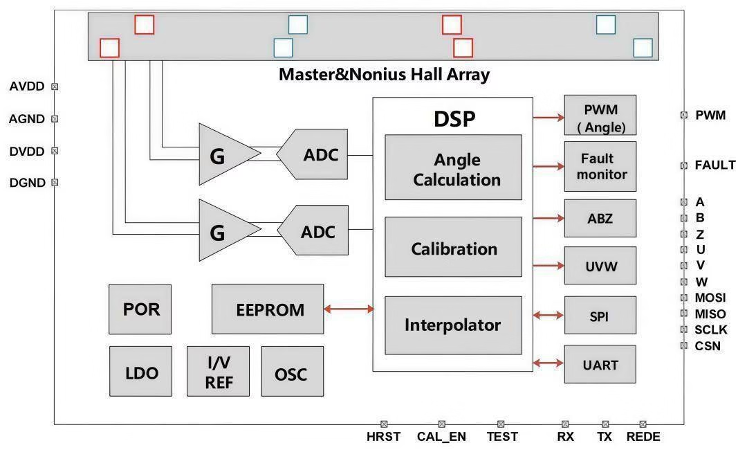
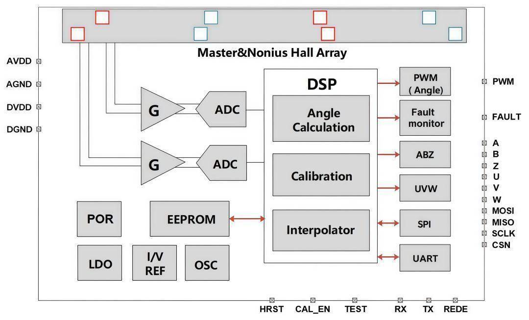
Vernier decoding needs a matched target. A periodic track alone repeats its pattern around the ring. The two-track relationship supplies the additional position information, so mechanical fit and a pole-pair count are only part of the ring specification.
Why are compact off-axis encoders difficult to design?
The challenge is to recover a stable angle from a small magnetic target inside a crowded electromechanical assembly. The NOVOSENSE interview highlights the combination of miniaturization, magnetic interference, signal processing and reliable feedback under changing operating conditions.
| Design challenge | Why it matters | What to evaluate |
|---|---|---|
| Small target and tight packaging | Ring dimensions, PCB space and the hollow shaft constrain the sensing geometry. | Usable track width, sensor location, field direction and clearance throughout rotation. |
| Motor fields and interference | The target field must be distinguished from fields generated by nearby magnets, currents and the drive electronics. | Position feedback with the motor energized across representative loads and operating states. |
| Runout and mounting variation | Eccentricity, tilt and gap variation change the field sampled by the Hall array. | Assembly tolerances and full-turn angle error in the intended mechanism. |
| Signal-chain and calibration errors | Signal imbalance, offsets and magnetic pattern variation affect the calculated angle. | The specified calibration procedure, repeatability and residual error after calibration. |
| Temperature and dynamic operation | Motor heating and changing operating conditions can affect the complete sensing assembly. | Cold/hot operation, speed changes and stable feedback over the application’s required range. |
Differential Hall sensing and motor-field interference
Differential Hall sensing compares signals from spatially separated Hall elements. This helps reject magnetic-field components that appear similarly at the sensing elements while retaining the changing target-field information.
The benefit depends on the field distribution and sensing arrangement. Nonuniform motor fields and local gradients can still affect the measurement. Differential sensing and calibration therefore need to be evaluated together with the ring, motor and final mechanical assembly.
The encoder’s role in a robot joint control loop
The encoder measures actual angular position and feeds it back to the controller. The controller compares that feedback with the commanded motion and adjusts the motor drive. Reliable joint control depends on the complete feedback loop, including sensing, communication, control computation and the motor.
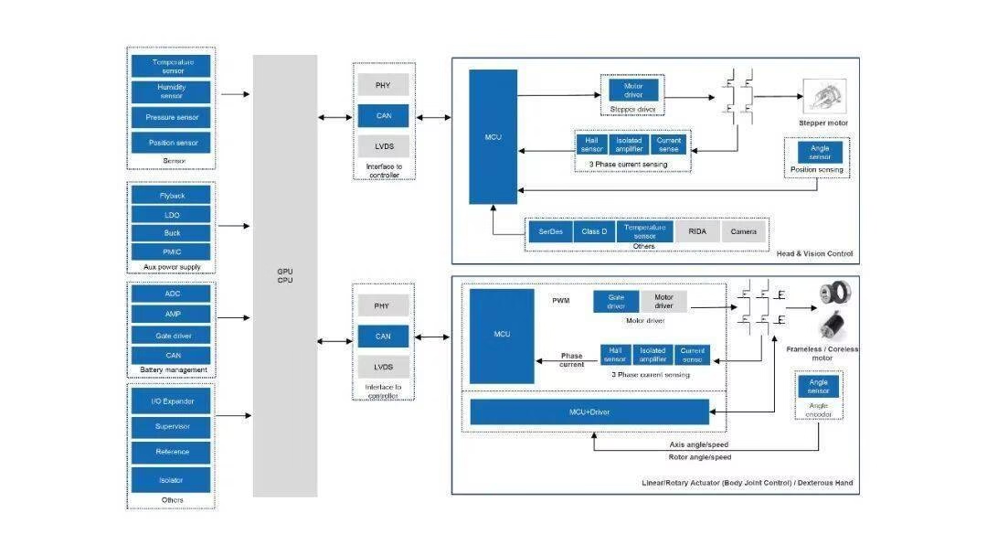
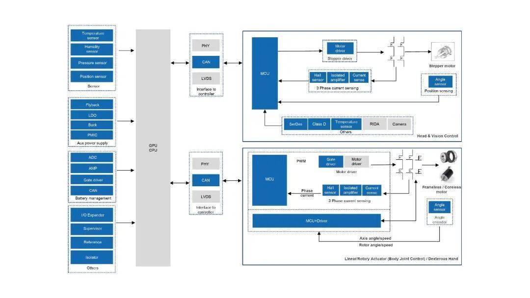
Technical context: adapted from the Xin Pian Jie Mi interview with NOVOSENSE sensor marketing director Xie Ben. The evaluation checks are OTV Sensing’s application guidance. Product-specific limits and qualification must be confirmed for the selected IC and assembly.
These design challenges explain why the ring-matching review and prototype enquiry checklist below cover both magnetic and mechanical requirements.
How to match a dual-track magnetic ring to NSM3502
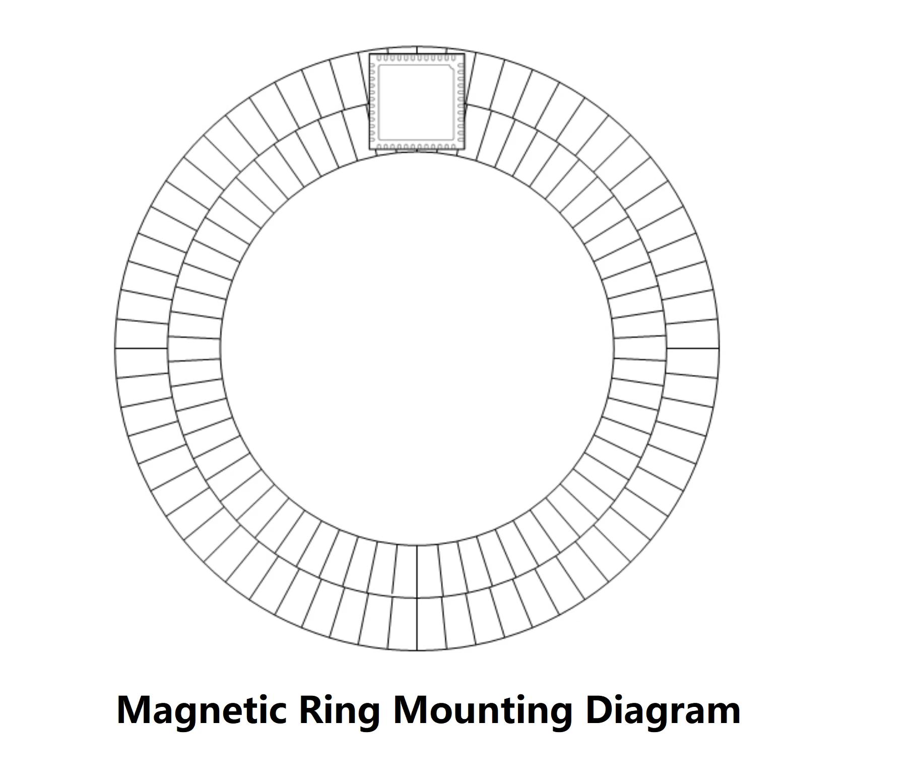
The NSM3502 uses a Hall-based off-axis sensing architecture with a dual-track vernier magnetic pattern. The sensor sits away from the rotation center, leaving the shaft bore available for cables and other mechanical needs.
A working assembly depends on more than the ring’s diameter. Review these elements together:
- Magnetic pattern: the track relationship, pole geometry and field direction required by the selected IC configuration.
- Sensor placement: PCB location, reading orientation and sensor-to-ring gap.
- Mechanical tolerances: ring alignment, runout, mounting method and available space.
- Operating conditions: speed, temperature and nearby magnetic interference.
Confirm the complete magnetic specification for NSM3502 before selecting a target designed for another encoder IC.
Review 16, 32 or 64 pole-pair configurations
OTV Sensing’s NSM3502 evaluation-board information lists dual-track target configurations with 16, 32 or 64 pole pairs. Choose a configuration together with the intended ring geometry and exact IC setup.
| Design choice | What to review | What to send |
|---|---|---|
| Pole-pair option | 16, 32 or 64 pole pairs within the applicable dual-track configuration; confirm both tracks and the IC setup. | Preferred configuration, exact IC part number and any existing magnetic drawing. |
| Ring envelope | Bore, outside diameter, thickness and room for mounting features. | Shaft and housing drawings, with fixed dimensions and adjustable ranges. |
| Readout geometry | Reading orientation, PCB position, operating gap and permitted runout. | Sensor location or an assembly section view. |
| System requirements | Target speed, operating temperature, electrical interface and required position accuracy. | Application requirements and the planned evaluation method. |
Scroll the table horizontally on smaller screens. The second-track pattern and magnetization parameters need confirmation for the selected NSM3502 configuration.
Use the magnetic encoder ring configurator to communicate standard-part preferences or a custom mechanical envelope. The submitted draft is a starting point for engineering review.
From magnetic ring selection to encoder integration
Define the assembly
Start with the shaft drawing, available space, PCB location and operating requirements. Mark dimensions that are fixed and those that can change.
Review the matched set
Review the IC, magnetic track configuration, ring dimensions and board together. Confirm the evaluation quantity, expected production demand and available supply options.
Evaluate in your mechanism
Check signal behavior and position performance in the intended mounting arrangement. Use the results for design verification and production preparation, refining the ring and assembly where needed.
Plan for system-level validation. IC resolution alone does not establish finished-encoder accuracy. Ring quality, sensing gap, alignment, runout and the final assembly all affect the result.
What to send for ring selection and quotation
- Mechanical drawing: ring ID/OD, thickness, mounting method, shaft dimensions and permitted runout.
- Magnetic requirements: intended pole-pair configuration, reading orientation, available sensing gap and any existing magnetization specification.
- Electrical requirements: exact NSM3502 part number, supply arrangement, required interface and PCB location.
- Application conditions: maximum speed, working temperature, nearby magnetic fields and required position accuracy.
- Project details: sample quantity, expected production quantity, evaluation schedule and delivery destination.
Send the drawing even if some values are still open. Mark the uncertain items so OTV Sensing can identify what needs confirmation or a bench test.
NSM3502 magnetic ring questions
Can I use a dual-track ring made for another encoder IC?
Compatibility requires agreement between the magnetic pattern, track relationship, field direction, sensing geometry and IC configuration. Send the existing ring specification and exact NSM3502 part number for review before treating it as a matching target.
How does OTV Sensing support different project stages?
Sample quantities and small-batch supply are OTV Sensing services for evaluation and pilot builds. For production planning, share the exact IC variant, expected annual quantity and delivery schedule so chip supply and magnetic target requirements can be reviewed. Project quantity does not define the NSM3502 or NSM350x family’s technical application scope.
Can I request chips, rings or a board separately?
Yes. Specify which items you need and the quantity required for your current development stage. OTV Sensing can review separate or combined supply requests; stock, pack format and delivery are confirmed in the quotation.
Does selecting 16, 32 or 64 pole pairs define the complete ring?
The pole-pair option is one part of the design. Both magnetic tracks, ring dimensions, reading orientation, gap and exact IC configuration must also be specified together.
Where can I find board specifications and interface information?
The NSM3502 evaluation-board product page contains the board overview and specification download. This guide focuses on off-axis sensing principles, magnetic target matching and application integration.
Discuss your NSM3502 or NSM350x encoder application
Send the exact IC variant, shaft/PCB drawing, magnetic track requirements, electrical interface and operating conditions. Include the quantity required now, expected annual demand and project schedule. OTV Sensing will review the sensing arrangement, matching target and available supply options.