
TMR position sensing converts changes in a magnetic field into electrical signals that can be processed into motion feedback. With NVE Corporation’s AET-Series sensors, a multipole ring or linear magnetic scale produces periodic Sin/Cos outputs; the magnet geometry and the interpolation electronics determine how those signals become useful position data.
This OTV Sensing application note explains the sensing principle, the difference between pole pitch and magnetic pitch, and the checks needed when matching an AET sensor to a magnetic target. For a broader component comparison, see our magnetic encoder IC selection page.
Start with the target’s pole pitch, not its overall diameter. The electrical period, bridge configuration, air gap and position reference must all suit the application. A small interpolation step is not the same as verified system accuracy.
How does TMR position sensing work?
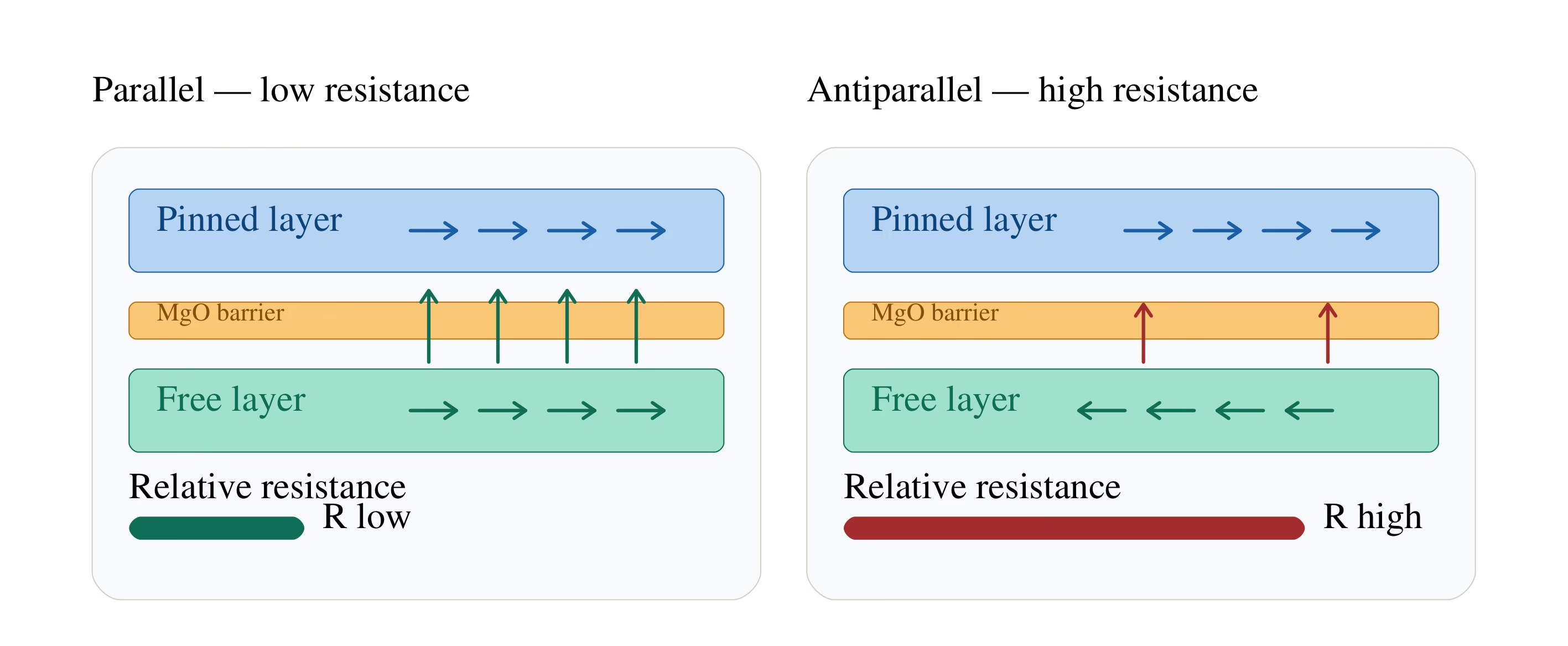
Tunneling magnetoresistance uses a magnetic tunnel junction: two ferromagnetic layers separated by a very thin insulating barrier. One layer provides a stabilized magnetic reference, while the other responds to the external field. Their relative magnetization changes the junction’s resistance through spin-dependent tunneling.
In a simplified picture, parallel alignment gives lower resistance and antiparallel alignment gives higher resistance. A practical sensor combines these elements with a bridge layout to convert the field pattern into a measurable voltage.
The sensor reads the target without physical contact. The complete assembly still needs an appropriate magnet material, mounting method, electrical design and environmental validation.
How AET Sin/Cos outputs become position feedback
AET devices provide analog sine and cosine channels. In a full-bridge part, these are separate differential bridge channels, rather than two independent phase signals taken from the two outputs of one bridge. Their phase relationship provides interpolation and direction information.
The controller samples the channels, corrects offset and amplitude imbalance, and calculates electrical phase using atan2. It must also track complete periods and establish a position reference. Serial outputs such as those discussed in our BiSS and SPI interface comparison belong to the downstream encoder electronics.
Electrical angle and mechanical angle are different
For a ring with p pole pairs, one revolution contains p electrical periods. If φ is the electrical phase normalized to 0–360° and k is the counted number of complete periods from a reference:
For example, with 32 pole pairs, one complete electrical cycle corresponds to 11.25° of mechanical rotation. Dividing a cycle into 1,000 interpolation steps gives a nominal step of 0.01125°. This is a calculated resolution example, not an AET accuracy specification.
A periodic analog signal does not identify a unique full-turn position by itself. Period counting, a reference mark or another suitable position-identification method is needed. An absolute encoder architecture must be designed and evaluated separately.
Pole pitch vs. magnetic pitch: match the target correctly
For this article, w is the width of one N or S pole, measured along the sensing path. This is the pole pitch used in NVE’s AET selection guidance. One complete N+S period has length λ = 2w, referred to as magnetic pitch.
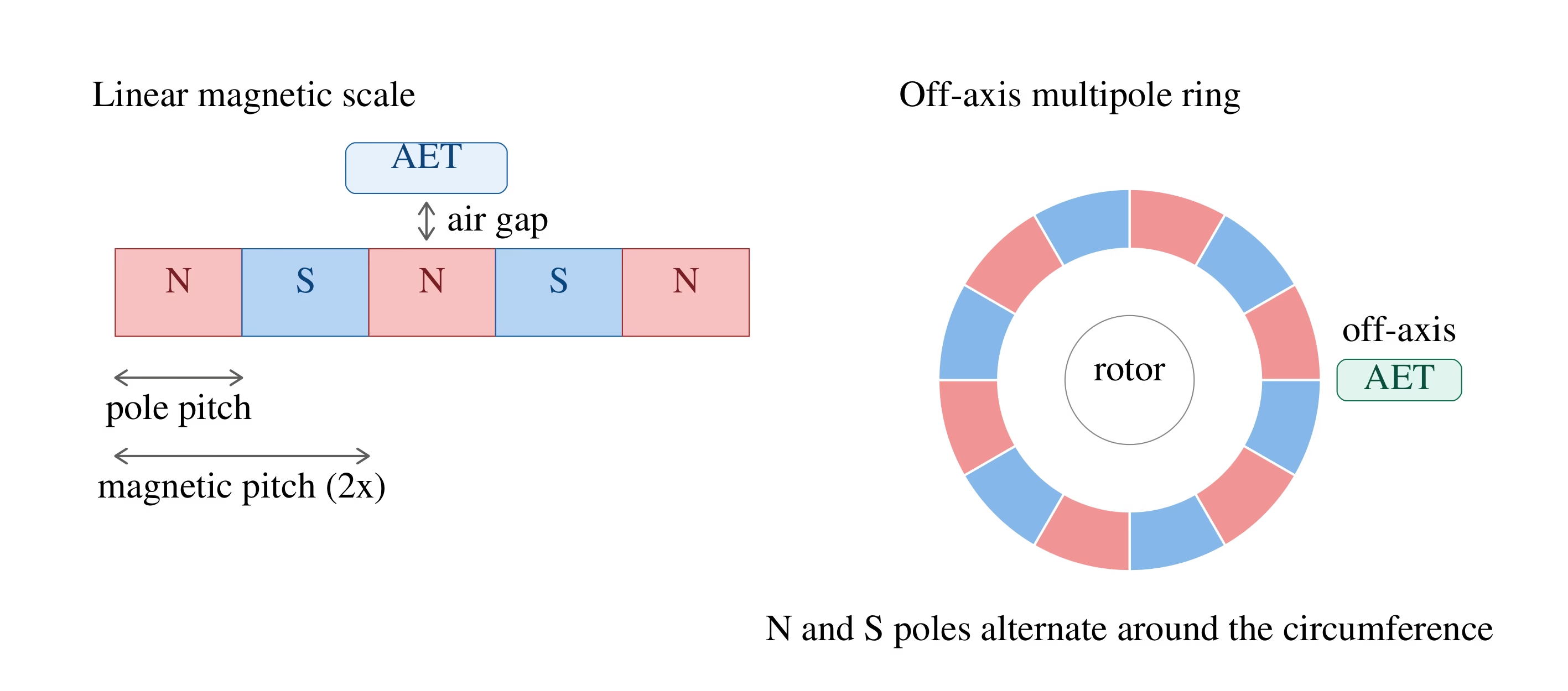
As a concrete example, a 1 mm pole pitch in normal operation corresponds to the AET100F-00E, with a 2 mm electrical period. A 2 mm pole pitch and a 2 mm magnetic period are different specifications. Always state which one appears on the magnet drawing.
Relating pole count to a rotary sensing diameter
For equal-width poles around a nominal sensing circle of diameter D:
Here D is the sensing-circle diameter, not automatically the ring’s outside diameter. For a linear scale, displacement from a reference is x = 2w × (k + φ / 360°). These are geometric relationships; target curvature, field quality and the sensor’s element spacing still need to be checked in the assembled design.
Selecting an AET-Series TMR sensor
NVE Corporation manufactures the AET-Series. OTV Sensing’s role in this application is magnetic target selection, dimensional review and coordination of the sensor–magnet pairing. Check the exact part’s current manufacturer documentation before finalizing a design.
| AET part | Bridge | Optimized pole pitch w | Magnetic period 2w | Package |
|---|---|---|---|---|
| AET050F-00E | Full | 0.5 mm | 1 mm | MSOP8 |
| AET075F-00E | Full | 0.75 mm | 1.5 mm | MSOP8 |
| AET100F-00E | Full | 1 mm | 2 mm | MSOP8 |
| AET120F-00E | Full | 1.2 mm | 2.4 mm | MSOP8 |
| AET500-02E | Half | 5 mm | 10 mm | SOIC8 |
Selection reference: NVE’s AET overview and the AET-Series datasheet. The magnetic-period column is calculated as 2w. Use the current datasheet’s optimized pitch rather than assuming older double-pitch recommendations apply.
Full bridge, half bridge and operating limits
Full-bridge versions provide differential outputs and common-mode rejection. Real installations still require checks for field gradients, alignment and magnetic interference. NVE notes that common-mode fields above approximately 1 mT can influence half-bridge versions.
The datasheet lists a −50 to +150°C sensor operating range and an operating frequency up to 350 kHz. These values do not establish the temperature rating of a magnet assembly or its permissible mechanical speed. Electrical frequency is p × rpm / 60 for a p-pole-pair ring.
NVE’s AG970-07E kit supports bench evaluation of AET parts with linear magnetic scales. A rotary target should also be tested in its intended geometry. For component-level comparisons beyond AET, review the encoder IC options.
Matching multipole rings and linear scales
Use the same pole-pitch definition for the sensor drawing, the magnet specification and the test report. For suitable target formats, explore OTV’s magnetic rings and encoder discs or magnetic linear scales and encoder tape.
- Reading geometry: distinguish radial-rim reading from face-pole reading, and align the sensor’s sensitive direction with the intended field component.
- Air gap: test signal amplitude, distortion and interpolation error across the complete gap range, including runout and assembly variation. There is no single gap value suitable for every target.
- Target quality: check pole-width variation, magnetization consistency, concentricity and local field shape at the sensor.
- Electronics: budget for ADC noise, sampling, channel gain, phase error and reference stability. Calibration must remain valid across operating conditions.
- Temperature and installation: validate the magnet, carrier and adhesive together. Our article on temperature and magnetic ring material selection provides related considerations.
Define acceptance limits using measured position error against a suitable reference. High output amplitude or a fine interpolation step alone does not demonstrate the final accuracy.
TMR and AET selection questions
Does an AET sensor provide absolute position at power-up?
Its Sin/Cos outputs repeat with the target’s magnetic period. Identifying a unique position over several periods requires additional reference information or a suitable system architecture. AET and the dual-track absolute systems discussed in our iC-MU ring design guide have different sensing and processing requirements.
Is the N-to-N distance the value used to select an AET part?
NVE’s normal selection guidance uses the single-pole pitch w. The N-to-N distance is the magnetic period 2w. Confirm the terminology on your target drawing before selecting a sensor.
Can a linear-scale sensor be used with a rotary ring?
AET devices support both application types, but a rotary implementation must account for the sensing diameter, curvature, magnetization and alignment. A matching nominal pitch is a starting point for evaluation.
What resolution or air gap can OTV guarantee from this article?
A system-specific result requires the selected sensor, target, electronics and installation conditions. Send the design requirements for review and sample evaluation rather than treating the article’s calculation examples as product guarantees.
Review your TMR magnetic target with OTV Sensing
For a custom magnetic encoder ring or linear target, send the AET part number, single-pole pitch, pole-pair count or travel length, OD/ID/thickness, reading direction, air-gap range, working temperature and required system accuracy.
You can use the online configurator to record ring dimensions. Choose “Other IC / readhead” and enter the AET part number; the listed standard rings need a separate sensor–target suitability review.
Engineering enquiries: thomas@otvsensing.com.