
ROBOT JOINT FEEDBACK · INDS09
INDS09 Same-Side Dual Absolute Encoder for Robot Joints
Two absolute angle channels in one compact inductive encoder. INDS09 combines one stator with two concentric rotor targets on the same sensing side for integration into robot joint modules.
Use the two rotor positions for motor-side and gearbox-output feedback when the joint mechanics bring both shaft motions to the encoder. Select the A/B shaft assignment to suit your design.
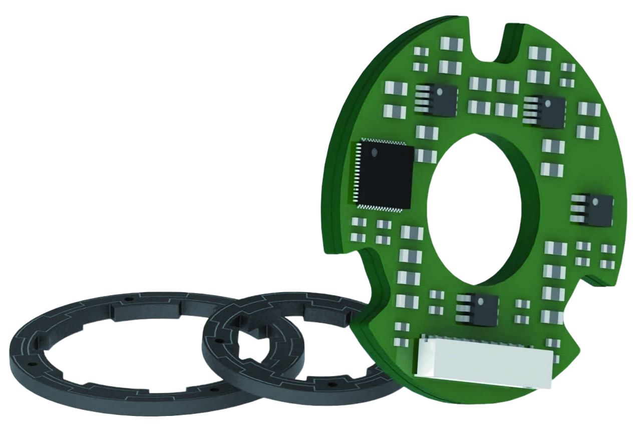
*Core thickness excludes the connector and mounting components. Use the section drawing to check the complete assembly envelope.
ENGINEERING QUICK GUIDE
Start with the joint. Follow the feedback path.
SAME-SIDE DUAL INDUCTIVE ENCODER
One stator, two rotor positions for robot joint feedback
A motor encoder reports the motor shaft angle. In a geared joint, the controller also benefits from measuring the actual output angle rather than calculating it only from the reduction ratio. Gearbox backlash, elastic deflection and assembly effects can separate those two values.
INDS09 provides separate signal groups for the outer and inner rotor targets. Attach the targets to the selected rotating members so the controller can use motor feedback and direct joint-position feedback in a dual-loop architecture.
What same-side means
The two concentric rotor targets face the same sensing side of the stator. They can rotate with different shaft members while sharing the stator footprint. This differs from an opposite-side arrangement with a rotor on each face of the stator.
Compare same-side INDS and opposite-side INDO configurations →
Shared 5 V supply and ground
Functional diagram, not a scaled mounting drawing. Assign outer A and inner B to the motor or output shaft according to the joint mechanics; the channel names do not define the shaft assignment.
APPLICATION FIT
Designed for compact robot joint modules and rotary actuators
Geared robot joints
Use motor-side angle and direct output angle in the controller. Compare the two feedback paths to investigate transmission backlash and compliance.
Lightweight robot axes
A nominal 25 mm outside diameter and approximately 5 g mass suit compact integration studies where separate encoder assemblies compete for axial space.
Integrated rotary actuators
A bearingless, hollow-bore structure gives the actuator designer control over the shaft support and target mounting. Both sensing faces must remain coaxial and parallel.
Check the mechanical arrangement first. Both shaft motions must be accessible to the two same-side targets. If the layout requires sensing on opposite faces, review the INDO dual encoder options.
INDS09 TECHNICAL DATA
Dual absolute encoder specifications
| Parameter | INDS09 specification |
|---|---|
| Sensing principle | Contactless inductive angle measurement |
| Architecture | One stator; outer rotor A and inner rotor B on the same sensing side |
| Angular resolution | 17 bit / 131,072 counts per revolution |
| Maximum static error | ±0.03° (±108 arcsec) |
| Repeat error | ±2 LSB |
| Maximum operating speed | 6,000 rpm |
| Measurement option | Single turn; 16-bit pseudo-multiturn option |
| Rotation direction | Clockwise increasing by default; configurable |
| Parameter | INDS09 specification |
|---|---|
| Nominal outside diameter | 25 mm |
| Stator aperture | 9 mm in section A–A |
| Nominal rotor bores | Inner B: 10 mm; outer A: 15 mm |
| Core thickness | 4.5 mm, excluding connector and mounting components |
| Axial sensing gap | 0.40 ± 0.10 mm |
| Permitted installation eccentricity | ±0.05 mm |
| Approximate mass | 5 g |
| Rotor inertia: inner / outer | 0.030 / 0.088 kg·mm² |
| Listed materials | FR-4 and SUS304 |
| Construction | Bearingless; separate bonded rotor mounting faces |
| Parameter | INDS09 specification |
|---|---|
| Supply voltage | 5 V DC ±5% (4.75–5.25 V DC) |
| Current consumption | ≤80 mA |
| Output options | SSI, BiSS-C, RS-422 serial or RS-485 serial |
| Connection | Side connector; SM10B-SURS-TF |
| Channel groups | Pins 1–4: outer rotor A; pins 5–8: inner rotor B |
| Power connections | Pin 9: GND; pin 10: +5 V; shared by both channels |
| Parameter | INDS09 specification |
|---|---|
| Operating temperature | −30 to +105 °C |
| Storage temperature | −55 to +125 °C |
| Relative humidity | 0–99% RH |
| Shock | 100 g / 11 ms |
| Vibration | 20 g, 10–2,000 Hz |
| Maximum stated protection level | Up to IP40 |
| EMC references | IEC 61000-6-2; IEC 61000-6-4 |
17-bit resolution is the number of distinguishable angle counts, not the absolute accuracy. A 17-bit count is about 0.00275°; the specified maximum static error remains ±0.03°. At that resolution, ±2 LSB corresponds to approximately ±0.00549°.
The open, bearingless assembly is intended for integration into a suitable joint enclosure. EMC entries are specification references; qualification conditions and enclosure requirements should be agreed for the final assembly.
INSTALLATION ENVELOPE
Mounting dimensions, rotor bores and sensing gap
The nominal rotor bores are 10 mm for inner rotor B and 15 mm for outer rotor A. Section A–A also identifies a 9 mm stator aperture. Check these features separately when laying out concentric shaft members.
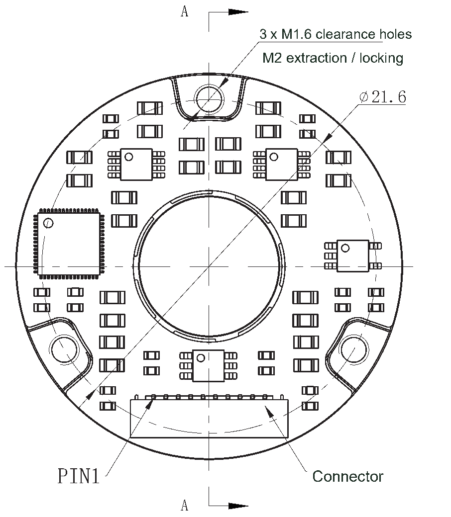
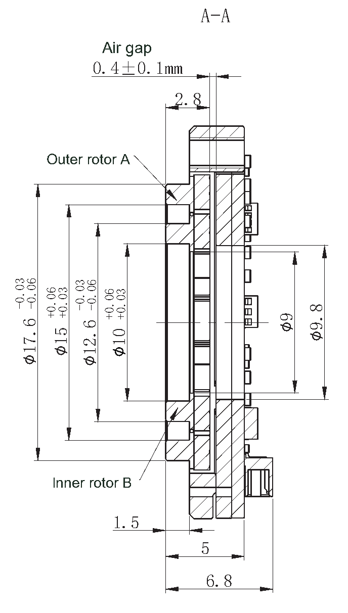
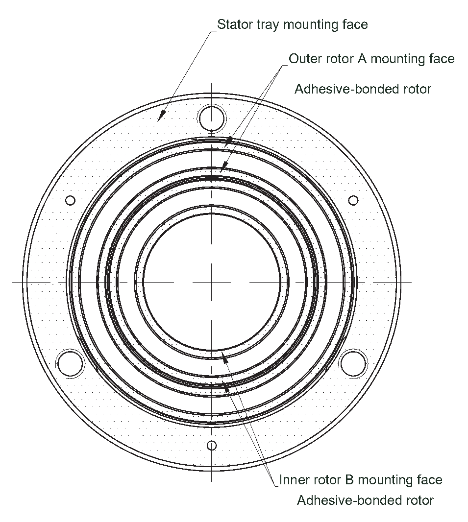
Separate bonded rotor mounting faces
Use the indicated mounting faces for the stator tray, outer rotor A and inner rotor B. Control installation eccentricity to ±0.05 mm and maintain parallel sensing faces throughout rotation.
Agree the adhesive, curing process, mounting stack and fastener arrangement before releasing a production drawing.
CONTROLLER INTEGRATION
SSI, BiSS-C and serial interface options
Select the interface when specifying the product. Protocol options are alternatives; data rates and frame definitions depend on the delivered configuration.
SSI / BiSS-C
- Host-driven clock with differential RS-422 electrical signaling.
- Binary position coding; stated signal delay below 50 µs.
- Maximum data update rate up to 20 kHz, configuration dependent.
- Confirm transmitted field width, alignment, clock settings and status interpretation; confirm CRC settings for BiSS-C.
RS-422 / RS-485 serial
- RS-422: 460,800 bit/s, 8E1; fixed 2,000 Hz update and 10-byte frames.
- RS-485: half duplex, 2.5 Mbit/s, 8N1; host-requested data.
- Keep outer A and inner B channel data assigned to the correct mechanical targets.
- Use the delivered firmware definition for parser, checksum and alarm handling.
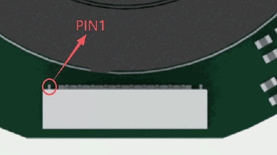
| Pins | Assigned function |
|---|---|
| 1–4 | Outer rotor A: separate clock/data or serial signal group |
| 5–8 | Inner rotor B: separate clock/data or serial signal group |
| 9 | Shared GND |
| 10 | Shared +5 V supply |
Specify angle resolution and communication format separately. The performance specification is 17 bit. The interface examples in the supplied document use different transmitted field lengths, so obtain the actual firmware frame width before implementing the controller parser. Do not apply one protocol’s update rate to another.
ASSEMBLY TO COMMISSIONING
Integrate the same-side dual encoder into your joint
Define the shaft mapping
Identify the motor and output shaft members. Assign them to outer A and inner B and confirm that both motions can reach the same sensing side.
Check the complete envelope
Review stator aperture, rotor bores, connector clearance and the installed stack. Use the section references instead of assuming 4.5 mm is the overall height.
Set gap and concentricity
Mount the faces coaxially and parallel. Check the 0.40 ±0.10 mm sensing gap and ±0.05 mm installation eccentricity over rotation.
Wire both signal groups
Verify pin 1, shared 5 V/GND and the selected protocol. Check direction and channel assignment before connecting position feedback to the control loops.
Run the installation check
Rotate through several revolutions with the supplied utility. Resolve gap-increase or gap-decrease indications using the approved shim arrangement before calibration.
Calibrate and verify
Apply installation compensation when required, restart the encoder, then verify zero, direction and position through the intended joint motion. Follow the delivered utility version.
ENGINEERING QUESTIONS
INDS09 dual absolute encoder FAQs
What does the INDS09 dual absolute encoder measure?
It provides angle feedback from two separate rotor targets using one stator. With suitable joint mechanics, the targets can follow the motor shaft and the gearbox output shaft. The outer A and inner B labels identify the targets, not a mandatory motor/output assignment.
How is same-side INDS different from opposite-side INDO?
INDS09 uses concentric targets facing the same stator side. An opposite-side design places rotor targets on different faces of a stator. Select the arrangement around shaft access, bore size and axial stack; compare the INDS and INDO dual encoder range.
Is this the same as a dual-track Nonius magnetic encoder?
No. INDS09 measures two mechanically separate rotor positions. A dual-track Nonius magnetic target typically uses two magnetic tracks to resolve one absolute position. Define the required shaft measurements before choosing the sensing architecture.
Is the complete encoder only 4.5 mm thick?
4.5 mm is the stated core thickness and excludes the connector and mounting components. Section A–A includes 5.0 and 6.8 mm stack references from different faces. Use the complete mounting drawing for clearance checks.
Does the pseudo-multiturn option retain turns with power removed?
The specification describes a 16-bit pseudo-multiturn option but does not establish unpowered turn retention. Confirm counting, reset and power-interruption behavior for the delivered configuration. Single-turn absolute position and retained multi-revolution position are different requirements.
Can the two angle signals be used to estimate joint torque?
A controller can compare motor-derived and directly measured output angle to study transmission deflection. A torque estimate also needs an appropriate stiffness model, calibration and dynamic treatment. INDS09 is specified as an angle encoder, without a direct torque measurement rating.
Do two output channels mean safety-rated redundancy?
Separate angle signal groups do not by themselves establish a safety-rated redundant system. The stator supply and ground are shared. Define the required diagnostic coverage and system architecture separately; no SIL or PL rating is specified in this product document.
What information should I send for a fit review?
Send the shaft or joint section drawing, required bore and axial space, motor/output speeds, required accuracy, controller interface, operating environment and expected quantities. Specify single-turn or pseudo-multiturn behavior and any power-cycle requirements.
TALK TO OTV SENSING
Review INDS09 for your robot joint module
Share your joint section drawing, shaft dimensions and feedback requirements. OTV Sensing can review the mechanical fit and available interface configuration with your engineering team.
Include INDS09, motor and output speeds, required accuracy, available axial space, interface and expected quantity in your message. Email: thomas@otvsensing.com.