
Rotary position & speed feedback
Incremental Magnetic Rotary Encoders
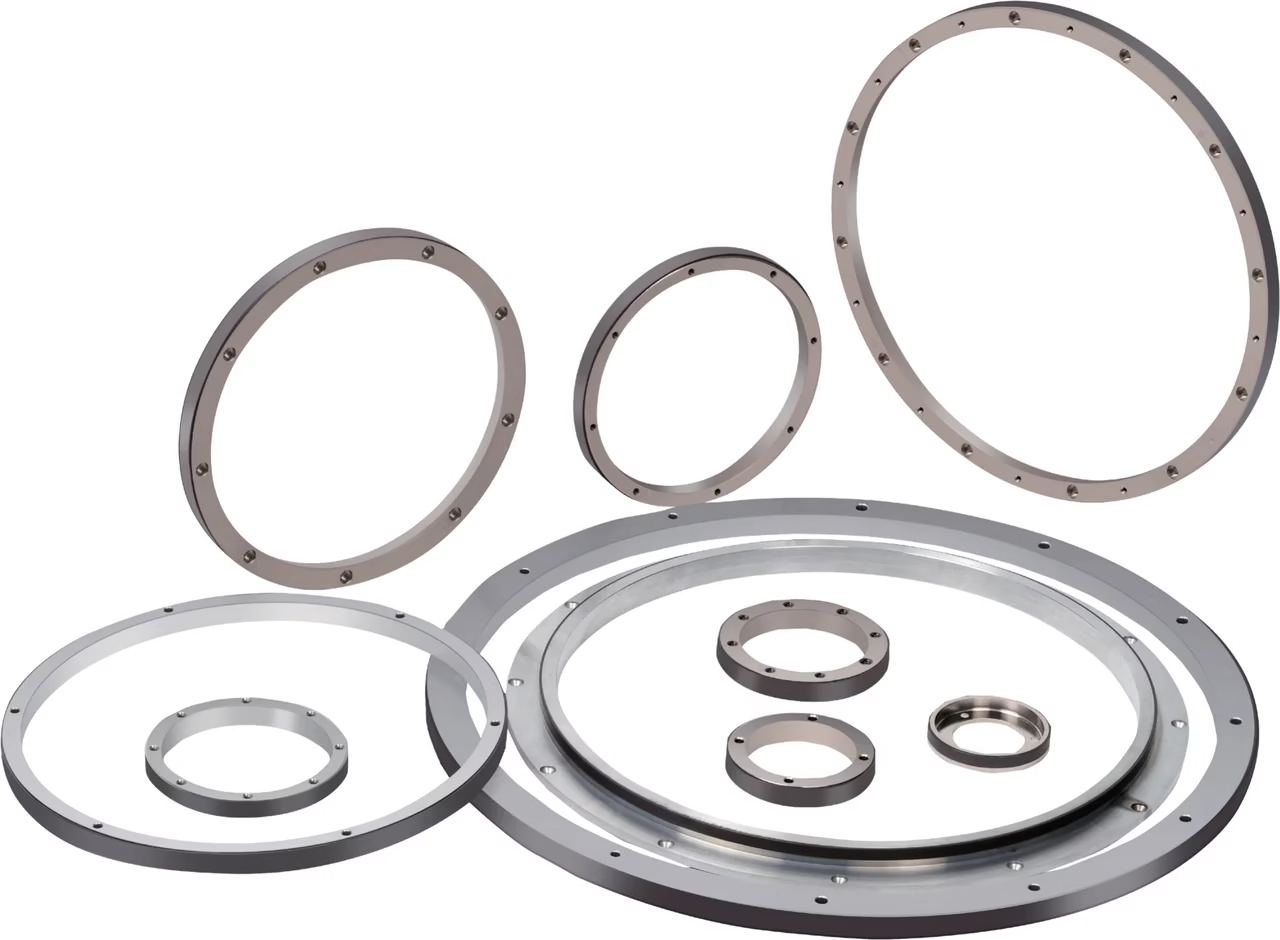
Two readhead architectures. A matched magnetic ring. Feedback that fits your machine.
OTV Sensing supplies non-contact, bearingless magnetic ring encoder systems for direct-drive motors, spindle assemblies and OEM rotary mechanisms. Choose an IP67 housed readhead or the compact icrm PCB rotary encoder, then select the ring geometry, A/B line count and reference function for your axis.
Start with the installation environment
Choose an IP67 readhead or a compact PCB rotary encoder
The readhead structure determines how the sensing electronics fit into the machine. The rotary ring is then selected around the available shaft space, magnetic sensing position and reference requirement.
Housed rotary readheads
icrp / icrl · icrt / icrr
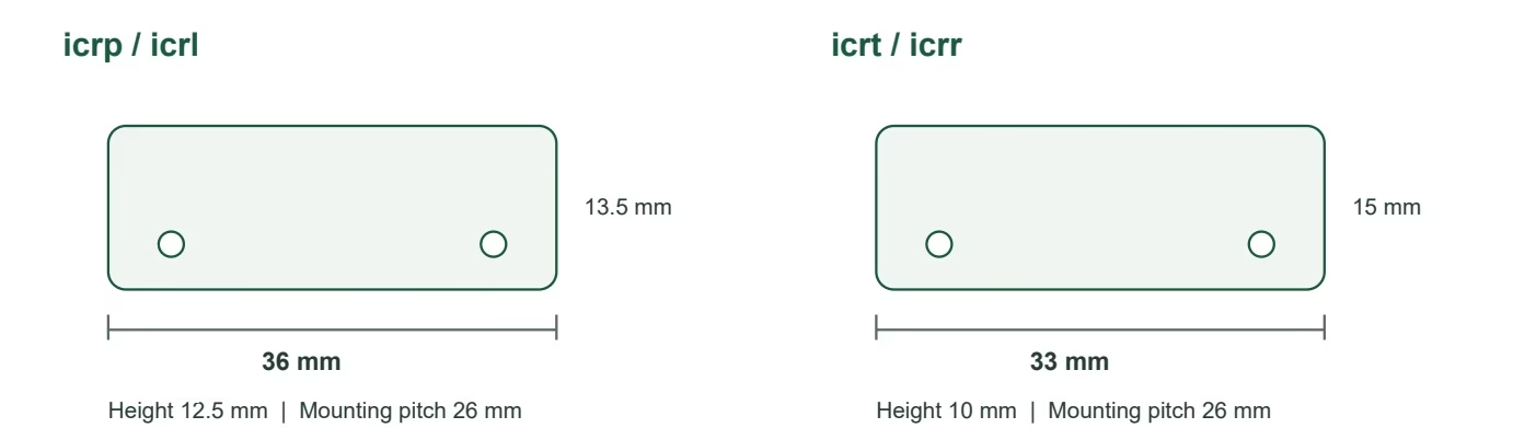
Sealed aluminum readheads for industrial rotary mechanisms where the sensing electronics need a protected housing. Two footprints let you trade installation width against height.
- 5 V supply, RS-422 differential output
- Periodic Z or single-turn unique Z variants
- 26 mm mounting-hole pitch
Ring route: IMR carrier rings support the housed-readhead layout. One example is IMR-104 with a 45 mm bore and 61.1 mm OD; other ring geometries are selected around the shaft and sensing position.
Compare housed modelsicrm PCB rotary encoder
Open readhead for embedded OEM integration
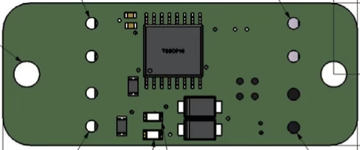
A 30 × 12 mm PCB readhead sits beside the magnetic ring, keeping the center bore available. The motor or machine enclosure provides protection for the integrated electronics.
- Compact sensing board with solder-pad connections
- Quadrature feedback with matched reference target
- Power and fault indication
Compact ring example: the icrm reference layout uses the IMR-101 geometry, with a 17 mm bore and 22.92 mm OD. Select the ring and board location together for the OEM assembly.
Review icrm integrationHow the system works
Magnetic ring feedback with quadrature A/B and reference Z
The magnetic ring rotates with the machine shaft. A stationary readhead senses the changing magnetic pattern and supplies A/B quadrature signals for relative position, speed and direction feedback.
A periodic Z repeats with the configured pattern. A unique Z identifies one reference position per revolution when the readhead and ring include the matching reference arrangement.
The bearingless layout uses the machine’s own shaft and bearings. Mechanical concentricity and the sensing gap therefore belong in the encoder design from the start.
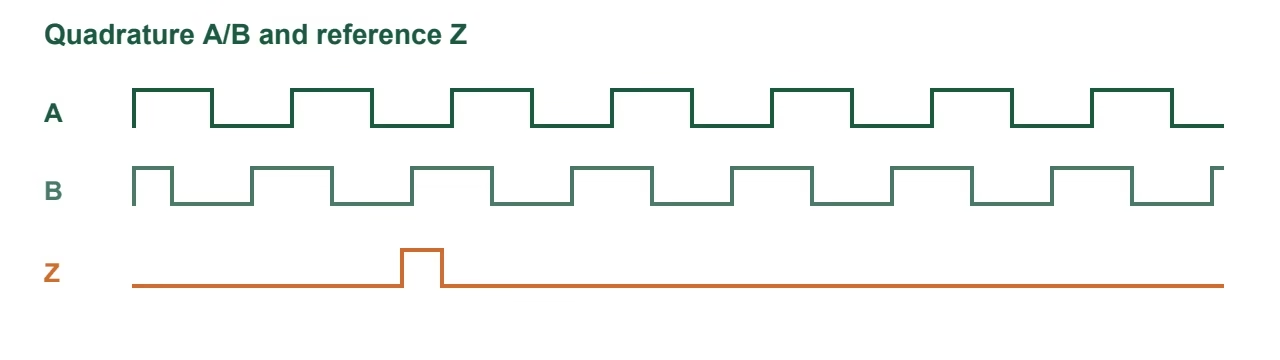
Reference selection: icrp / icrt use periodic Z; icrl / icrr and icrm support a single-turn unique Z with a matching target.
Compare the sensing hardware
Rotary encoder readhead specifications
IP67 housed readheads: icrp, icrl, icrt and icrr
| Parameter | icrp / icrl | icrt / icrr |
|---|---|---|
| Structure | Sealed aluminum housing, IP67 | Sealed aluminum housing, IP67 |
| Dimensions L × W × H | 36 × 13.5 × 12.5 mm | 33 × 15 × 10 mm |
| Mounting-hole pitch | 26 mm | 26 mm |
| Supply voltage | 5 V ±5% | 5 V ±5% |
| Current at 25°C | 60 mA maximum | 60 mA maximum |
| Output | A/B/Z differential options, RS-422 | A/B/Z differential options, RS-422 |
| Reference function | icrp: periodic Z icrl: unique Z with reference-mark ring | icrt: periodic Z icrr: unique Z with reference-mark ring |
| Sensing gap | Below 1 mm; target setting 0.50 ±0.10 mm | Below 1 mm; target setting 0.50 ±0.10 mm |
| Peripheral speed at finest listed setting | Up to 8 m/s | Up to 8 m/s |
| Operating temperature | −30 to +80°C | −30 to +80°C |
| Storage temperature | −40 to +105°C | −40 to +105°C |
| Cable | 0.5 m standard; custom lengths and termination options | 0.5 m standard; custom lengths and termination options |
icrm PCB rotary encoder: compact by design
For an embedded motor or OEM rotary assembly, icrm provides the sensing function on an open 30 × 12 mm board. It uses a 5 V supply connection and differential A/B/Z output options, with an operating temperature range of −30 to +80°C. The mounting drawing shows two Ø2.2 mm holes.
Plan the support surface, sensing-center location, cable strain relief and enclosure together with the chosen magnetic ring. The compact PCB route is useful when a separate readhead housing would consume valuable integration space.
Select the rotating target
IMR and IMT incremental rotary magnetic rings
Use the ring’s inner diameter to start the mechanical selection, then compare outer diameter, thickness, output line settings and the unique-index option. IMR identifies the carrier-ring range; IMT identifies the thin-wall geometries.
17 ring geometries
| OTV model | ID mm | OD mm | Thickness mm | Min PPR | Max PPR | RPM at max PPR | Unique index Z |
|---|---|---|---|---|---|---|---|
| IMR-101Carrier ring | 17 | 22.92 | 10 | 36 | 36,864 | 6,600 | Optional |
| IMR-102Carrier ring | 30 | 51 | 7.5 | 80 | 81,920 | 2,900 | No |
| IMR-103Carrier ring | 40 | 47.5 | 5.5 | 76 | 77,824 | 3,100 | No |
| IMR-104Carrier ring | 45 | 61.1 | 10 | 96 | 98,304 | 2,400 | Optional |
| IMR-105Carrier ring | 54 | 72.57 | 10 | 114 | 116,736 | 2,000 | Optional |
| IMR-106Carrier ring | 68 | 81.49 | 10 | 128 | 131,072 | 1,800 | Optional |
| IMR-107Carrier ring | 106 | 122.2 | 10 | 192 | 196,608 | 1,200 | Optional |
| IMR-108Carrier ring | 130 | 150.2 | 10 | 236 | 241,664 | 950 | Optional |
| IMR-109Carrier ring | 140 | 162.97 | 14 | 256 | 262,144 | 930 | Optional |
| IMR-110Carrier ring | 187 | 203.7 | 10 | 320 | 327,680 | 700 | Optional |
| IMR-111Carrier ring | 209 | 229.2 | 10 | 360 | 368,640 | 650 | Optional |
| IMR-112Carrier ring | 240 | 282.1 | 13.7 | 400 | 409,600 | 550 | No |
| IMR-113Carrier ring | 285 | 325.94 | 12 | 512 | 524,288 | 460 | Optional |
| IMR-114Carrier ring | 310 | 343.77 | 10 | 540 | 552,960 | 430 | Optional |
| IMR-115Carrier ring | 395 | 450.7 | 15 | 708 | 724,992 | 330 | Optional |
| IMT-116Thin-wall | 448.1 | 450.7 | 10 | 708 | 724,992 | 330 | Optional |
| IMT-117Thin-wall | 466.83 | 469.43 | 10 | 738 | 755,712 | 320 | Optional |
No listed ring matches these filters. Send OTV Sensing your required bore and installation space to discuss a custom geometry.
Other dimensions or a different mounting arrangement?
Share your shaft drawing, required bore, available carrier space and reference requirement. OTV Sensing can discuss a custom rotary ring and matching readhead configuration for your assembly.
Discuss a matched ring and readheadEngineering selection support
Specify your rotary encoder system
Send a drawing or describe the space around your shaft. OTV Sensing can help select the readhead architecture, ring geometry and output configuration together.
- Ring ID, OD and available thickness
- Readhead mounting space and enclosure
- Required PPR and maximum rpm
- Periodic or unique index requirement
- Controller input, supply and cable length
Prefer email? lucy@otvsensing.com
Design around the axis
Applications for magnetic ring encoder systems
Direct-drive and torque motors
Place the magnetic ring around the shaft while preserving the center opening for cables or services. Compare the available stator space with a housed or PCB readhead layout.
Start with: bore, carrier space, concentricity and controller feedback format.
Spindle and rotary drive assemblies
Select line count and rotational speed together. Ring diameter sets the peripheral speed seen at the sensing track, while the selected PPR sets the pulse rate sent to the controller.
Start with: maximum rpm, selected ring diameter, PPR and index behavior.
Embedded OEM rotary mechanisms
Integrate the compact icrm PCB rotary encoder into a protected assembly, or select a housed readhead when the sensing electronics need their own sealed enclosure.
Start with: PCB support, sensing-center location, protection and service access.
From selection to commissioning
Plan ring geometry, PPR and controller bandwidth together
Define the mechanical envelope
Check the ring ID, OD and thickness against the shaft and carrier. Locate the sensing surface and readhead center, then plan concentricity, gap and thermal movement.
Select the reference arrangement
Choose periodic Z or a single-turn unique Z to suit the homing strategy. Match the ring’s reference feature to the chosen readhead.
Check the signal path
Review power at the readhead, cable routing, differential receiver wiring, shielding and the input pulse rate supported by the controller.
Validate the assembled axis
Check direction, full-turn count, reference detection and signal stability across the intended speed, gap and temperature range.
Convert line count into useful feedback
Here, PPR means A-channel cycles per revolution. A controller using ×4 quadrature decoding counts four edges for each cycle.
Counts/rev = 4 × PPR
A-channel frequency = PPR × rpm / 60
For example, IMR-106 at 131,072 PPR provides 524,288 counts per revolution with ×4 decoding. The nominal output increment is approximately 0.0006866°.
Resolution defines the output increment. Ring quality, concentricity and final mechanical integration also determine the achieved position accuracy.
Read the hollow-shaft installation guideIncremental magnetic rotary encoder FAQ
What is an incremental magnetic rotary encoder?
It is a rotary position and speed feedback system that reads a magnetized ring without contact. The readhead supplies quadrature A/B signals; a configured Z reference can establish the machine datum during homing.
What is the difference between an IP67 readhead and a PCB rotary encoder?
The icrp, icrl, icrt and icrr readheads use sealed aluminum housings. The icrm PCB rotary encoder is a compact, open readhead that integrates into the OEM assembly and uses the machine or motor enclosure for environmental protection.
Does icrm use a full annular PCB around the shaft?
icrm uses a small PCB readhead positioned beside a separate rotating magnetic ring. The shaft passes through the ring; the PCB sits at the sensing position rather than forming a full annular encoder board.
Which models provide a single index per revolution?
icrl and icrr provide a single-turn index with a matching reference-mark ring. icrm also supports a unique index with the corresponding target. icrp and icrt provide periodic Z. Select the readhead, reference feature and controller homing strategy together.
How do PPR and quadrature counts differ?
PPR on this page means A-channel cycles per mechanical revolution. A controller using ×4 quadrature decoding counts four edges per cycle, so 131,072 PPR produces 524,288 counts per revolution. Output step size and system accuracy are different specifications.
What magnetic ring bore sizes are available?
The 17 listed IMR and IMT ring geometries cover inner diameters from 17 to 466.83 mm. Select the mechanical size, index requirement and output configuration as a matched encoder system. Contact OTV Sensing for other dimensions or mounting requirements.
Can an incremental encoder report absolute position immediately after power-up?
An incremental system needs a machine reference strategy after power-up. If your application requires immediate absolute position feedback, review OTV Sensing’s absolute hollow-shaft magnetic encoder systems.