
Engineering guide · OTV Sensing
iC-MUE Encoders: Magnetic Ring Design and iC-MU200 Compatibility
A hollow-shaft encoder has to fit the motor before it can measure anything. The bore, ring carrier, PCB position and operating gap all compete for space. The iC-MUE gives designers useful flexibility—but a successful design still starts with a matched magnetic target.
This guide explains the iC-Haus iC-MUE encoder, compares the practical design choices with iC-MU200, and uses MAG1000 and MAG1001 to show how the magnetic ring and sensor position fit together.
How the iC-MUE Off-Axis Absolute Encoder Works
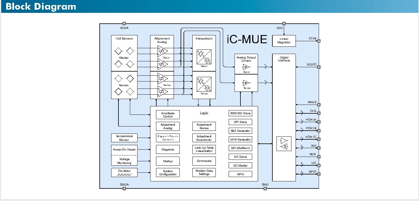
The iC-MUE is a Hall-based absolute encoder System-on-Chip for rotary and linear position feedback. In a hollow-shaft rotary design, the IC sits beside the shaft and reads two magnetized tracks on a ring. This leaves the shaft center available for cables, tubing or other mechanical functions.
The Master and Nonius tracks have different numbers of magnetic periods. Their relative phase identifies absolute position, while interpolation resolves the finer movement within a period. The decimal Nonius engine supports more flexible pole-pair combinations than the familiar 16/15, 32/31 and 64/63 arrangements. MAG1000 uses 20/19 pole pairs; MAG1001 uses 24/23.
- Read the targetHall arrays scan the Master and Nonius tracks.
- Condition the signalsSignal adjustment and gain control establish the operating point.
- Resolve positionNonius evaluation, interpolation and correction produce position data.
- Report to the controllerAbsolute, incremental and commutation outputs serve the motion system.
Differential magnetic scanning helps suppress external interference fields. Its effectiveness still depends on the field environment and assembly. Evaluate the sensor near the actual motor, steel components and current-carrying conductors.
iC-MUE Specifications: Read the Conditions Alongside the Numbers
| Magnetic pattern | Dual-track Nonius, 8–64 master pole pairs; three-track expansion is available. |
|---|---|
| Master pole width | Hall sensors optimized for nominal 2.00 mm poles. |
| Single-turn resolution | Up to 22 bit; the fact sheet gives 21 bit with a 44 mm code disc at 32 pole pairs. Three-track systems can reach up to 26 bit. |
| Typical absolute accuracy | <0.04° at 32 pole pairs, after calibration and LUT linearization. |
| Maximum rotary speed | Up to 12,000 rpm at 32 pole pairs. |
| Power supply | Main supply 3.0–5.5 V; typical current 65 mA. I/O supply 2.25–5.5 V. |
| Ambient temperature & package | −40 to +125°C; QFN48, 7 × 7 mm, thickness 0.9 mm. |
| Absolute data interfaces | BiSS up to 10 MHz or SSI up to 4 MHz; SPI up to 12 MHz. Check port allocation when combining outputs. |
| Other outputs | Programmable FlexCount ABZ; UVW for motors with 1–32 pole pairs; native-CPR Sin/Cos outputs. |
| Adjustment & diagnostics | Automatic adjustment by pin or command, gain control, eccentricity compensation, LUT linearization, I²C configuration and diagnostics. |
Resolution is the number of reported position increments. Accuracy describes agreement with the true position. A 21-bit or 22-bit output does not establish the accuracy of the assembled encoder. The <0.04° figure above is a conditional typical value from the supplied fact sheet.
The fact sheet is preliminary. Use the current iC-Haus iC-MUE documentation when releasing the electrical design.
iC-MUE vs iC-MU200: What Changes in the Design?
| Design consideration | iC-MU200 | iC-MUE |
|---|---|---|
| Master pole width | Nominal 2.00 mm | Nominal 2.00 mm |
| Common two-track configurations | 16/15, 32/31 and 64/63 pole pairs | Decimal Nonius; 8–64 master pole pairs, including the 20/19 and 24/23 examples below |
| Single-turn resolution | 18, 19 or 20 bit for 16, 32 or 64 master pole pairs, with the applicable filtering configuration | Up to 22 bit; 21 bit at 32 pole pairs in the fact-sheet example |
| Signal adjustment | Offset, amplitude and phase conditioning; Nonius synchronization adjustment | Automatic adjustment with integrated eccentricity compensation and LUT linearization |
| UVW motor commutation | 1–16 motor pole pairs | 1–32 motor pole pairs |
The shared 2.00 mm master pole width is a useful starting point for a migration review. Compatibility also depends on track geometry, pole-pair pattern, sensor orientation, chip position and the available field over the working gap.
Can an Existing iC-MU200 Magnetic Ring Be Reused?
Some targets are explicitly specified for both devices. For example, iC-Haus lists the MU37S 45-32N as a two-track axial target for iC-MU200 and iC-MUE. That is a specific shared-target example, rather than evidence that every iC-MU200 ring is interchangeable.
For an existing design, check the target drawing and sensor placement first. Then review the PCB pinout, power rails, register map, interface timing and calibration procedure. A shared package size or pole width does not establish a pin-compatible replacement. The iC-MU200 comparison follows the manufacturer’s published family features.
iC-MUE Magnetic Ring Requirements: Start with the Scan Geometry
Magnetic layout
Specify the Master/Nonius pole pairs, scanning diameters, track widths, relative pattern and sensor orientation. Confirm magnetic signal quality at the sensing plane.
Mechanical layout
Specify bore, OD, thickness, carrier, shaft fit and PCB mounting. Include runout, tilt, assembly tolerances and thermal movement in the gap budget.
The physical ring OD, the two scanning diameters and the chip-center mounting radius are separate dimensions. Locating a PCB from the ring OD alone can put the Hall arrays in the wrong place. Use the target-specific layout and package reference.
| Axial scanning | OD 20–85 mm; ID 5–70 mm. |
|---|---|
| Radial scanning | OD 15–80 mm; ID 7–72 mm. |
| Typical reference air gap | 0.60 mm +0.30/−0.20 mm. Confirm the working gap for the selected target and assembly. |
These ranges describe design envelopes. They do not imply that every OD/ID combination is feasible. The pole pattern, usable track width, field strength and available installation space must agree.
Automatic gain control and correction functions help during commissioning. They do not recover a missing track or eliminate the need to control runout and alignment. Keep sufficient signal and synchronization margin throughout the operating range.
MAG1000 vs MAG1001: Two Practical iC-MUE Ring Layouts
Both targets use two axial, bipolar-magnetized tracks in an injection-molded PA6/hard-ferrite ring. The larger MAG1001 accommodates a different shaft and requires a different sensor mounting radius and pole-pair setting.
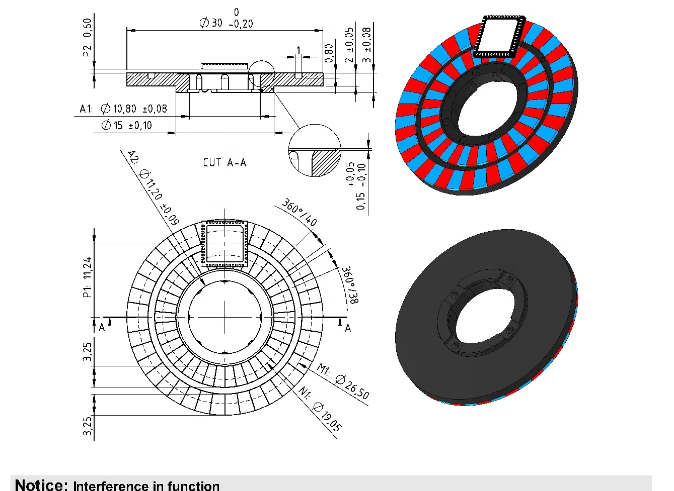
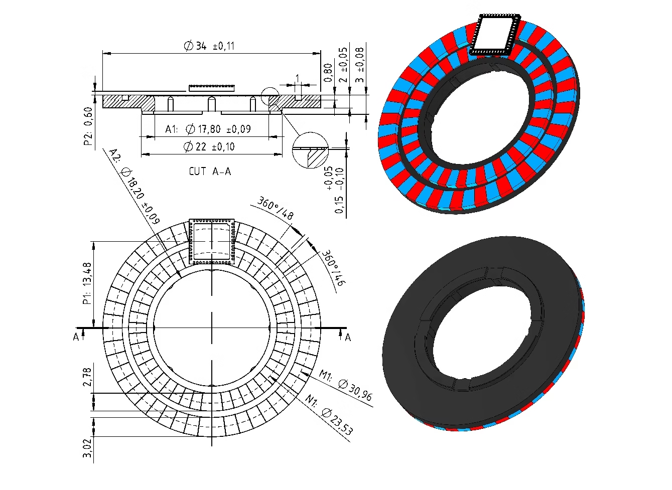
| Parameter | MAG1000 | MAG1001 |
|---|---|---|
| Outer diameter | 30 mm (+0/−0.20 mm) | 34 ±0.11 mm |
| Nominal shaft diameter | 11.0 mm | 18.0 mm |
| Master / Nonius pole pairs | 20 / 19 | 24 / 23 |
| Master scanning diameter M1 | 26.50 mm | 30.96 mm |
| Nonius scanning diameter N1 | 19.07 mm | 23.53 mm |
| Chip-center radius P1 | 11.24 mm | 13.48 mm |
| Package-to-magnet gap P2 | 0.60 mm nominal | 0.60 mm nominal |
| Press-ridge diameter A1 | 10.80 ±0.08 mm | 17.80 ±0.09 mm |
| Bore-hole diameter A2 | 11.20 ±0.09 mm | 18.20 ±0.09 mm |
| Typical weight | 3.9 g | 4.3 g |
| Pole-pair configuration | SYS_PP = 0x14 | SYS_PP = 0x18 |
| Scanning mode | SYS_LIN = 0 (rotary axial) | SYS_LIN = 0 (rotary axial) |
The nominal shaft diameter, press ridge A1 and bore hole A2 describe different features. They should not be substituted for one another in a fit calculation. Likewise, preserve the drawing-defined sensor position when moving between these target sizes.
For the wider product overview, see our iC-Haus off-axis and linear magnetic encoder solutions. OTV Sensing can discuss a matched or custom ring when these mechanical layouts do not fit your application.
Using iC-MUE for Absolute Linear Position Measurement
The same chip also supports a straight magnetic scale. Master and Nonius tracks encode position along the axis; the IC configuration and target layout must match linear scanning.
Two-track scale
The fact sheet specifies a maximum absolute measurement length of 256 mm.
Three-track scale
The maximum absolute measurement length extends to 4,096 mm using an additional iC-MUE in the expanded system.
Define the required usable travel, track layout, readhead space and end margins before choosing the scale. Rotary angular accuracy figures do not specify linear displacement accuracy. Validate the completed linear axis against its own accuracy and repeatability requirements.
Compare complete products and magnetic targets in our linear magnetic scale and encoder tape collection.
A Practical Validation Sequence for the Chip and Magnetic Ring
- Review the drawingConfirm track pattern, scan diameters, sensor reference and the complete gap tolerance stack.
- Check raw signalsInspect amplitude, balance and phase through a full revolution or the intended travel.
- Adjust and calibrateRun the appropriate adjustment and correction procedure in the final mechanical assembly.
- Verify the systemMeasure error and repeatability; repeat power cycles, speed tests and environmental checks.
For motor feedback, test with the motor powered as well as unpowered. For retained multiturn position, confirm the external counting or retention architecture and the behavior during power loss. The ability to report single-turn absolute position does not establish power-off multiturn tracking.
Record the target part, PCB revision, sensor configuration, calibration data and test conditions together. These records make sample approval and later mass-production troubleshooting far more useful.
Custom iC-MUE Magnetic Rings from OTV Sensing
OTV Sensing can supply magnetic encoder ICs, precision magnetic rings and encoder components at different integration levels. For iC-MUE and iC-MU200 projects, we review the magnetic target together with the chip and mechanical installation.
- Target pattern: matched Master/Nonius tracks, pole-pair count and scanning geometry.
- Mechanical envelope: custom bore, OD, thickness, mounting features and carrier arrangement.
- Material selection: injection-molded ferrite or NBR/HNBR-based magnetic compounds, selected for the required field, temperature and environment.
- Carrier evaluation: aluminium and suitable steel constructions, with their effect on the magnetic circuit considered in the design.
- Sample support: review signal quality, mounting tolerances and calibration results before agreeing the mass-production specification.
Explore our standard magnetic rings and Nonius encoder discs, custom magnetic encoder rings, and magnetic encoder IC supply and selection service.
Discuss Your iC-MUE Encoder Design
Send OTV Sensing your IC model, shaft drawing, available ring space, axial or radial scanning arrangement, gap budget, temperature range, output interface and accuracy target. If you are upgrading an existing iC-MU200 design, include its target drawing and PCB layout so we can review what can be retained.
iC-MUE Design Questions
Is iC-MUE a rotary or linear encoder IC?
It supports both rotary and linear absolute position feedback. The magnetic target, sensor orientation and configuration must match the application.
What is the iC-MUE resolution?
The fact sheet specifies up to 22-bit single-turn resolution, with a 21-bit example at 32 pole pairs and a 44 mm code disc. Three-track systems can reach up to 26 bits. These are resolution figures, not assembled-system accuracy guarantees.
Can every iC-MU200 magnetic ring work with iC-MUE?
Compatibility must be checked for the specific target. Some rings are specified for both chips, but shared nominal 2.00 mm master pole width alone does not establish complete target or PCB compatibility.
Can OTV Sensing customize an iC-MUE magnetic ring?
Yes. OTV Sensing can review custom ring dimensions, carrier design and magnetic track geometry against the chip configuration and mechanical installation, with sample validation for the intended assembly.