
Optical, magnetic, and inductive encoders all measure rotary position. The useful question is which sensing principle fits your mechanics, environment, and control system.
Use this guide to narrow the field, then confirm the shortlisted model against its drawing and test conditions.
Three ways to read rotary position
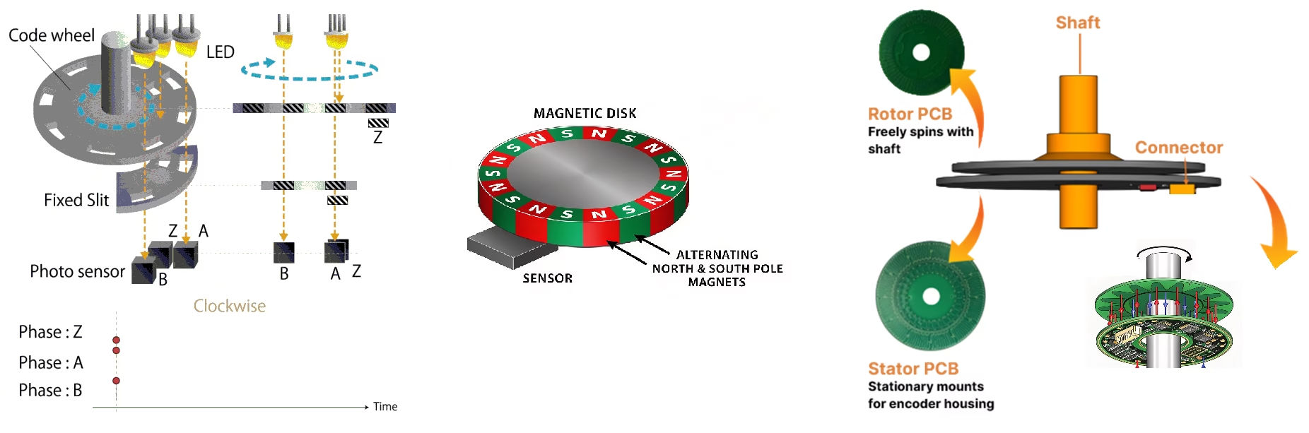
All three technologies measure rotary position, but each detects a different physical change to infer that position. The sensing method helps determine which disturbances matter and which installation details deserve attention.
Optical
A readhead detects a pattern on a disk or scale. Optical designs span incremental and absolute feedback and can support fine measurement when the optics, scale, alignment, and processing are specified for the job.
Check: sealing, contamination, alignment, shock, vibration, and service access to the scale.
Magnetic
A sensor such as Hall, AMR, or TMR reads a magnetic pattern. These designs are often compact and tolerant of dirt on the sensing surface, which can help when protecting an optical path is difficult.
Check: stray fields, target quality, air gap, temperature behavior, and the specified field limits.
Inductive
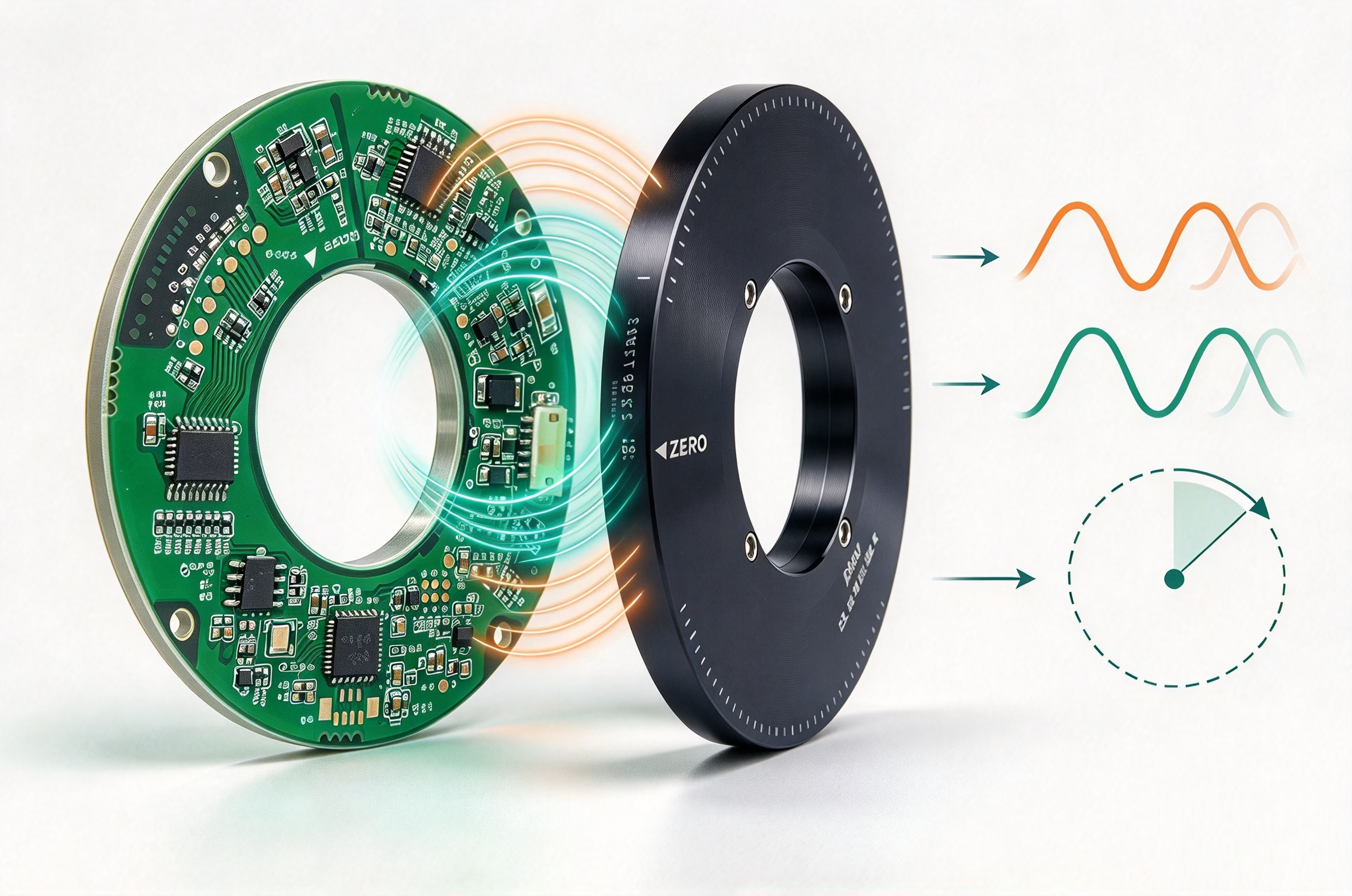
A conductive target modulates coupling between coils as it rotates. There is no optical track to read and no permanent-magnet code ring in the sensing target. Hollow-bore and low-profile layouts can be a good mechanical fit.
Check: nearby conductive metal, target geometry, gap, eccentricity, PCB layout, and model-specific limits.
Match the technology to the disturbance
This matrix is a first-pass screen, not a blanket rating. The exact encoder design, enclosure, mounting, and environment determine the result.
| Application condition | Optical | Magnetic | Inductive | What to verify |
|---|---|---|---|---|
| Dust or oil mist | Protect the scale and optical path | Often tolerant at sensing face | No optical path; check material compatibility | Sealing, contamination type, cleaning method |
| Strong nearby magnetic fields | Usually not a sensing input | Field is the measurement signal | Different sensing quantity; still test the assembly | Motor field, current, field limits, installed error |
| Conductive metal around sensor | Usually a secondary mechanical concern | Usually a secondary magnetic-layout concern | Can alter coil coupling | Housing, fasteners, ground planes, target shape |
| Very low axial height / hollow shaft | Depends on disk and readhead packaging | Depends on ring and sensor geometry | Ring PCB layouts may suit low-profile bores | Full stator and rotor drawing, cable route, gap |
| High accuracy over temperature | Scale, optics, and mounting stability | Magnet behavior and compensation | Coil geometry, electronics, target, calibration | Accuracy definition, range, test conditions |
A selection workflow that works at the drawing stage
Then match the interface and electrical levels to the controller. If more than one technology still fits, build a short prototype plan and compare position error on the real mechanical assembly.
Five checks before approving a model
Keep performance terms separate
Resolution is the output increment. Accuracy is the error from true position under stated conditions. Repeatability is consistency when returning to a position. Bit count alone does not establish accuracy.
Choose incremental or absolute
Incremental feedback may require homing. Absolute feedback reports position within its specified single-turn or multi-turn range. Check what happens on power loss and restart.
Check both rings and the gap
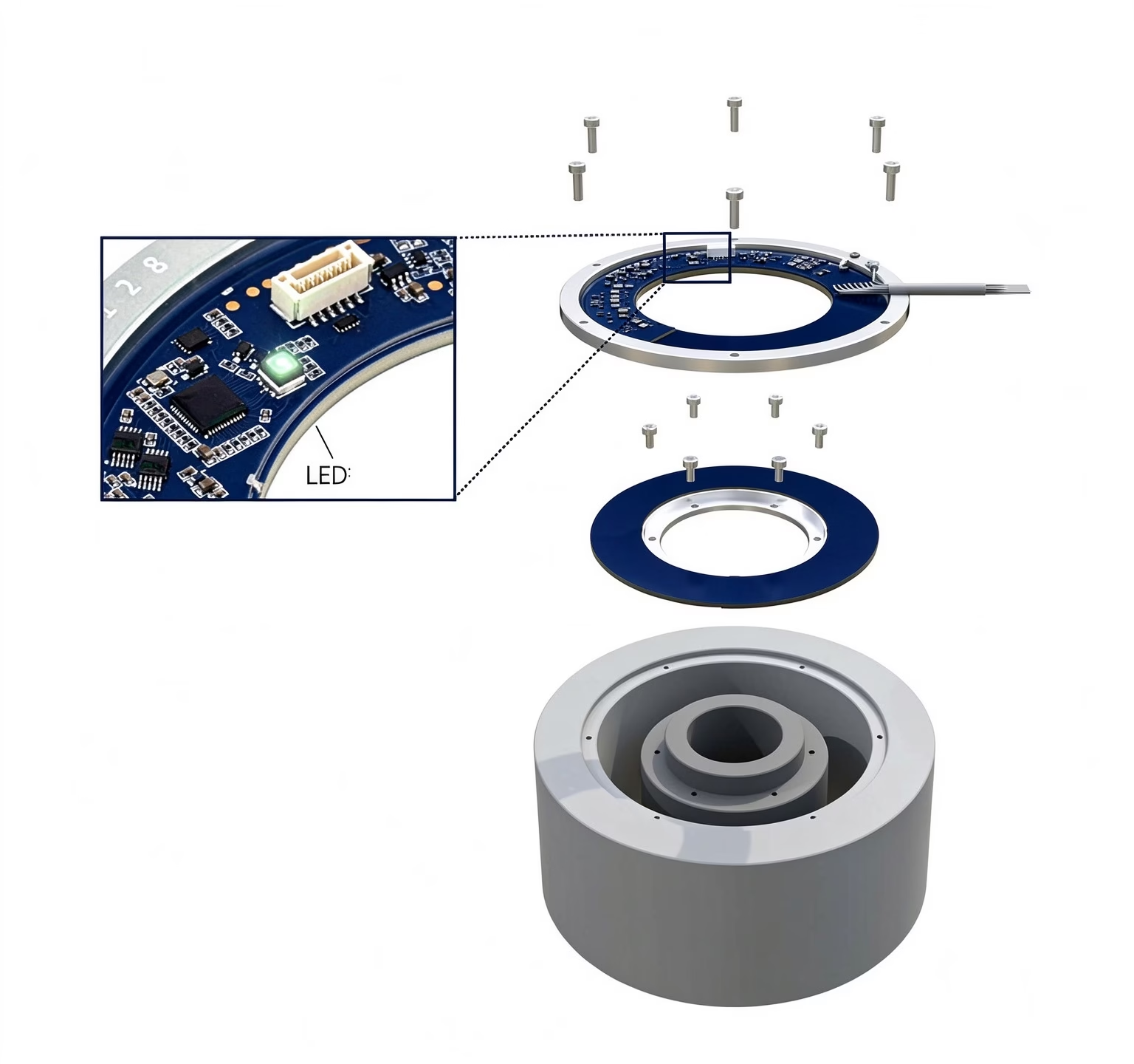
For hollow encoders, compare stator and rotor dimensions separately. Confirm axial space, shaft clearance, mounting access, cable route, allowed gap, and runout.
Verify the exact interface
Confirm protocol variant, voltage levels, connector, cable length, update rate, and diagnostics. A protocol name alone is not a wiring specification.
Test the installed axis
Measure error through a full revolution with the real motor, housing, fasteners, and cable routing. Check repeatability, thermal drift, startup, and electrical noise.
A practical shortlist
Consider optical when…
The measurement requirement points to an optical solution and the scale and readhead can be mounted and protected within the product’s environmental limits.
Consider magnetic when…
Compact integration and contamination tolerance matter, and the magnetic environment and temperature range can be controlled or verified.
Consider inductive when…
A non-contact hollow-bore or low-profile package is useful, or permanent magnets are undesirable. Include nearby metal, target geometry, and gap in the first design review.
There is no universal winner. The strongest choice is the one supported by a requirement sheet and a test on the assembled axis.
OTV inductive encoder families
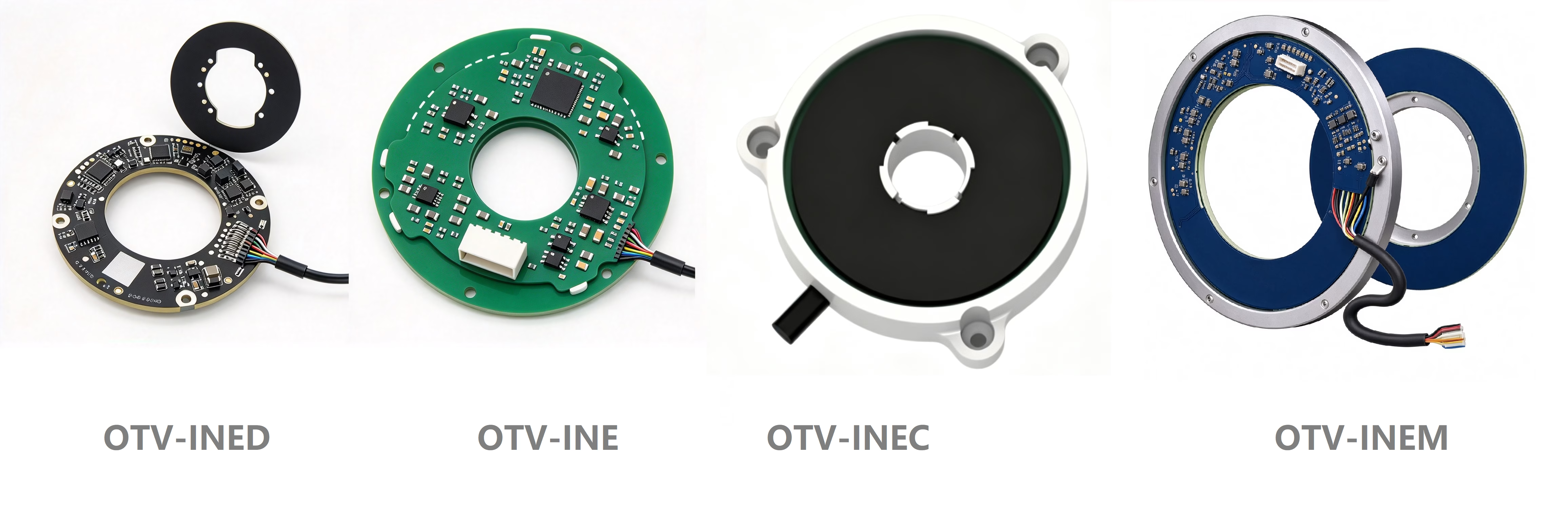
OTV’s four inductive series cover compact rotary feedback, harsher industrial environments, rotary tables, and hollow-bore configurations. The dimensions below summarize the models listed on each product page; range endpoints do not mean every intermediate size is available. Check the model table and drawing for the exact part.
OTV-INE 13 standard models
Compact, high-resolution absolute rotary feedback.
OTV-INEC 9 standard models
Rugged configurations for demanding installations.
OTV-INEM 3 rotary-table sizes
For rotary tables and precision rotary stages.
OTV-INED 29 configurations
Hollow-bore absolute rotary position feedback.
Frequently asked questions
Is an inductive encoder always better near an electric motor?
Not automatically. Inductive sensing does not use a permanent-magnet target, which can help in some motor assemblies. Nearby conductive structures and installed geometry can still affect coupling. Check model limits and test the complete assembly.
Does higher resolution mean better positioning accuracy?
No. Resolution is the output step size; accuracy is the error relative to true position under specified conditions. Shaft runout, mounting alignment, compliance, control behavior, and calibration can also limit system performance.
Which encoder is best for a dirty environment?
That depends on the contaminant and product sealing. Magnetic or inductive designs may avoid an exposed optical path, but the exact IP rating, temperature range, chemical compatibility, and mounting still matter.
What should I include in a recommendation request?
Include shaft or bore size, outer diameter and axial height, required accuracy and resolution, single-turn or multi-turn requirement, speed, interface, temperature, contamination, vibration, and nearby magnetic or conductive parts.