
Absolute Optical Linear Encoders
OTV-OPE open optical encoder systems pair a coded glass or metal scale with a compact readhead to report axis position directly after power-up. Select the scale material, maximum scale length, accuracy, resolution and BiSS-C connection around the machine – not just a headline resolution.
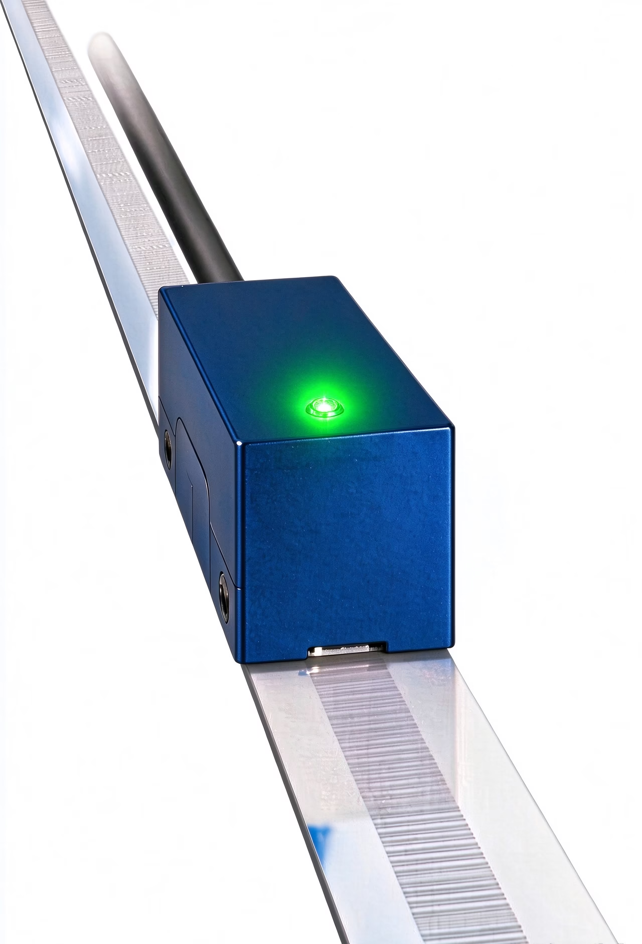 Absolute readhead and linear scale assembly
Choose the encoder around the axis
An absolute linear encoder solves a different problem from a motor-mounted rotary encoder: it measures the moving axis directly and reports its position without first searching for a reference mark. That can simplify restart behavior and expose errors from the transmission between motor and load.
Where it fits
- CNC and machine-tool linear axes
- Linear motors, precision stages and positioning slides
- Automated measurement, inspection and production equipment
- Machines that need axis position immediately after power-up
What engineers need to resolve
- Does the scale cover the full physical travel plus installation end allowances?
- Will the selected scale material meet the machine’s accuracy and thermal requirements?
- Does the motion controller support BiSS-C and the required signal wiring?
- Can the exposed optical scale be protected from chips, coolant, oil film and handling damage?
A coded scale and a scanning readhead
The scale carries the absolute position pattern. The readhead illuminates and images that pattern, processes the position data, then sends the result to the controller over a serial interface. Unlike an incremental-only system, the absolute code provides a position value without requiring the axis to first cross a reference mark.
The OTV-OPE source material describes an open optical construction. It keeps the system compact for integration, while making scale cleanliness, mounting geometry and protection part of the machine design.
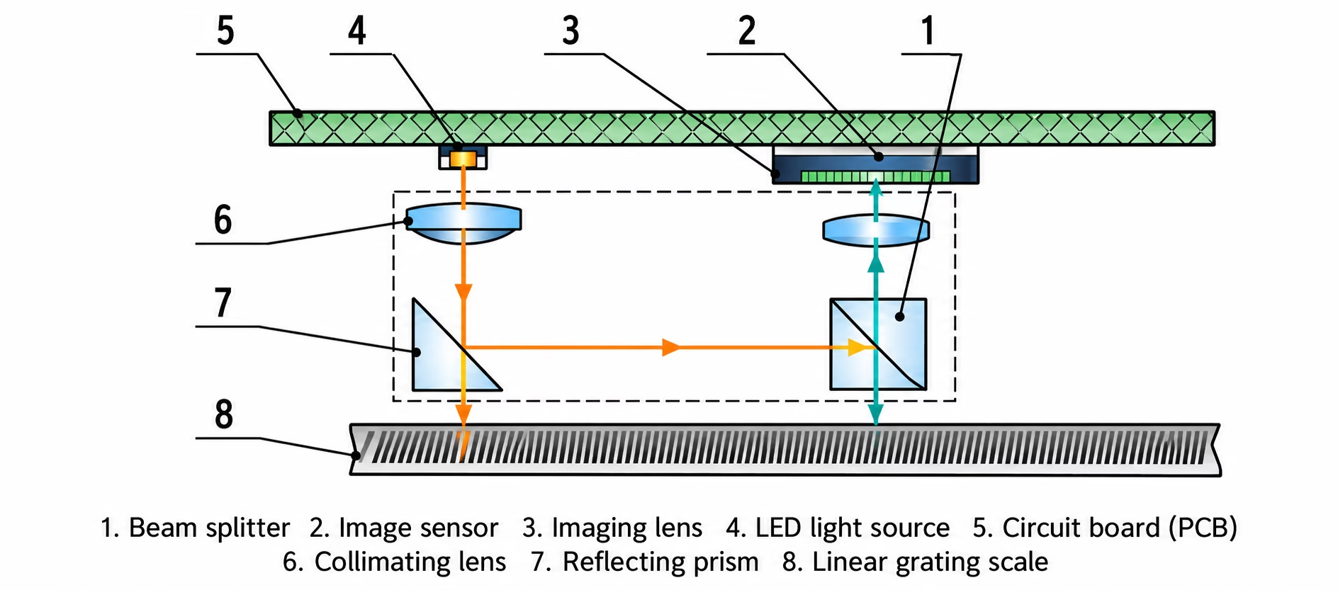 Coded scale offer absolute position through optical scan / BiSS-C output
OTV-OPE series configurations
The collection is organized by scale material.
| OTV collection identifier | Scale type | Maximum scale length* | Listed accuracy | Maximum resolution | Typical selection cue |
|---|---|---|---|---|---|
| OTV-OPE-GL | Glass scale | 450 mm | +/-2 um | 5 nm / 28 bit | Choose when the stated accuracy and fine resolution are the primary requirements. |
| OTV-OPE-MT | Metal scale | 1,300 mm | +/-8 um | 10 nm / 27 bit | Choose when a longer scale is needed within the listed product range. |
*Maximum scale length shown in the supplied product parameter sheet; actual usable measuring travel depends on the scale/readhead arrangement and end allowances. Shorter lengths are available by customization. Confirm the exact length and code with OTV before ordering.
OTV-OPE-GL | Glass scale
Listed accuracy is +/-2 um with 5 nm maximum resolution. Use this configuration when the application benefits from the glass-scale accuracy grade and the required scale length is within the listed limit.
Consider: support and mounting flatness, temperature behavior of the machine structure, and protection from direct contamination.
OTV-OPE-MT | Metal scale
The supplied parameter table lists a maximum scale length of 1,300 mm and +/-8 um accuracy, with 10 nm maximum resolution. It is the longer-range configuration in this product set.
Consider: datum strategy, mounting method, thermal expansion of the scale and the machine, and the chosen usable travel.
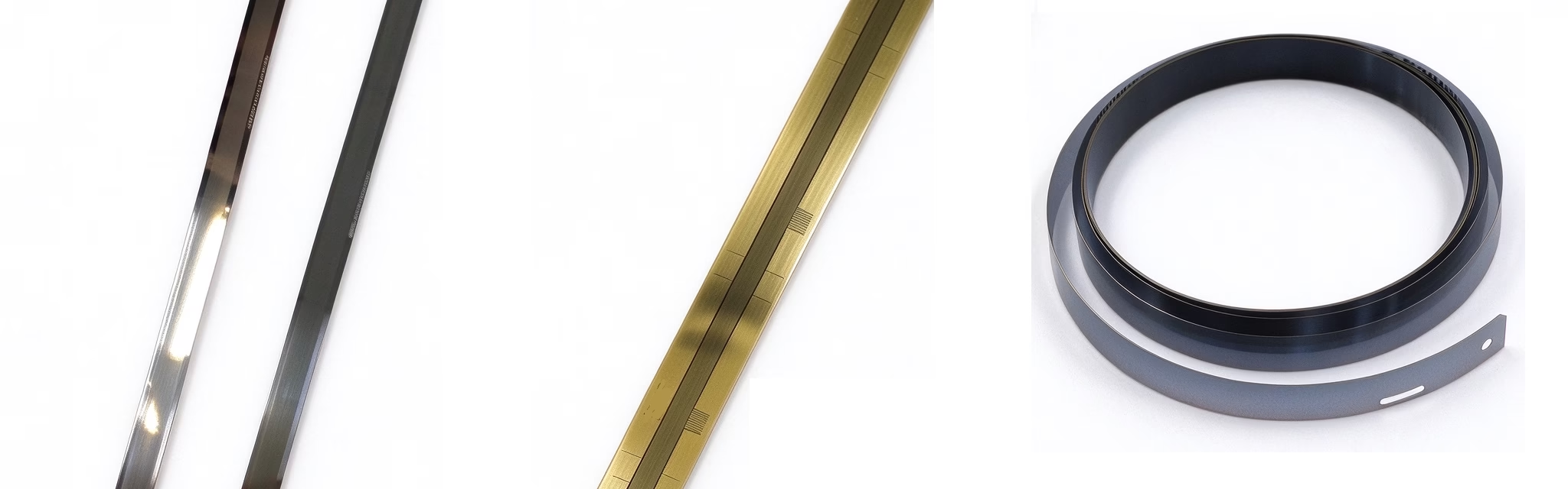
OTV-OPE absolute optical encoder specifications
Use the table as a first-pass selection reference. Figures below are transcribed from the supplied OTV product materials; confirm the selected model code and test conditions against the final datasheet.
| Parameter | Specification / options | Selection note |
|---|---|---|
| Measurement | Absolute linear position | Position value is available after power-up without a homing traverse. |
| Scale graduation | 40 um | Scale pitch is not the same as output resolution or system accuracy. |
| Scale material | Glass or metal | Accuracy and maximum scale length differ by scale type. |
| Listed accuracy | Glass: +/-2 um; metal: +/-8 um | Verify the specified measuring length and installation conditions. |
| Maximum resolution | Glass: 5 nm (28 bit); metal: 10 nm (27 bit) | Resolution is the smallest output increment, not guaranteed system accuracy. |
| Maximum speed | 360 m/min (6 m/s) | Confirm controller update rate and data-cycle timing at the required speed. |
| Interface | BiSS-C serial; 4 Mbps listed | Check controller support, clocking, cable length and signal receiver requirements. |
| Supply | 5 V nominal (4.5-5.5 V); 5 V +/-0.5 V listed | Use the voltage limits and wiring requirements for the chosen configuration. |
| Current consumption | 150 mA typical; 210 mA standard; 350 mA maximum | Allow for maximum draw in the controller power budget. |
| Output wiring | BiSS-C MA / SLO; differential RS-485 receiver recommended in source material | Confirm pinout, termination and receiver circuit before cable release. |
| Operating temperature | Options shown: -10 to +70 deg C; -30 to +70 deg C; -40 to +70 deg C | Temperature range is configuration dependent; confirm model-code option. |
| Protection | IP64 / IP30 options listed | Confirm which enclosure/configuration carries the required rating. |
| Humidity | <90% RH, non-condensing | Keep moisture and condensation away from the exposed scale. |
| Environmental resistance | Vibration: 55-2,000 Hz; operating acceleration up to 300 m/s2 listed | Confirm test axes, duration and the exact configuration in the released datasheet. |
Four checks before you specify an absolute linear encoder
Define travel
Measure required axis stroke, then include the scale length and end clearances required by the installation. Specify the maximum scale length separately from usable travel.
Set the error budget
Compare encoder accuracy with the machine’s total error budget. Include mounting, thermal expansion, structure, alignment and controller effects.
Match the controller
Confirm BiSS-C support, position word format, clock rate, cable/pinout, input receiver and power capacity before selecting the cable assembly.
Review the environment
Check chips, coolant, oil, dust, vibration, temperature and condensation. An open optical scale needs a realistic protection and maintenance plan.
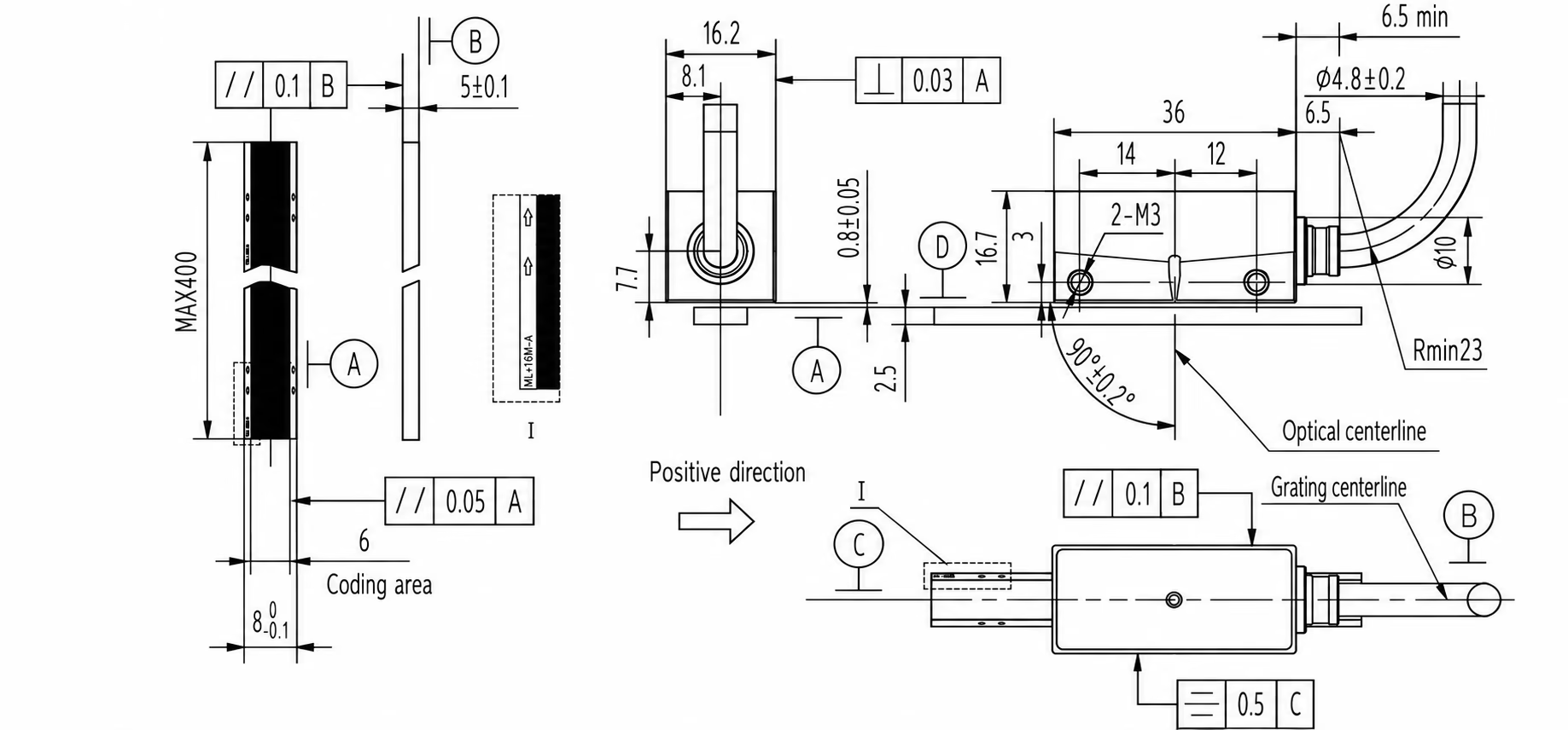 Readhead alignment, scale mounting datum
Absolute vs. incremental linear encoders
| Question | Absolute encoder | Incremental encoder |
|---|---|---|
| Position after power-up | Encoded position is available without traversing a reference mark. | Position is tracked from counted motion; a reference procedure may be required to establish machine coordinates. |
| Controller requirements | Requires a compatible absolute serial interface and data format. | Requires compatible incremental signal inputs and counter/interpolation support. |
| Best fit | Axes where restart state, recovery time or direct position knowledge matters. | Systems where incremental feedback meets the homing and control requirements. |
| Key trade-off | More interface/data-format coordination and typically higher system complexity. | Homing strategy and accumulated position state must be managed by the machine. |
The right choice depends on the control architecture, required restart behavior and total measurement budget – not on absolute or incremental alone.
OTV-OPE selection FAQs
Does the listed scale length equal usable axis travel?
No. The product parameter sheet gives a maximum scale length. Usable travel can be shorter because the readhead needs end allowances and installation space. The sheet notes that shorter lengths can be customized; specify the required travel and mounting arrangement when requesting a quote.
What is the difference between resolution and accuracy?
Resolution is the smallest change represented in the output; accuracy describes how close measured position is to the true position over the specified range and conditions. A 5 nm output increment does not mean +/-5 nm system accuracy.
Which OTV-OPE scale should I choose?
The supplied table lists glass scale at +/-2 um accuracy and up to 450 mm scale length, and metal scale at +/-8 um and up to 1,300 mm. Start with required usable travel and accuracy, then confirm the final scale length and machine installation.
Can the encoder report position immediately after power-up?
Yes. The system is specified as absolute and uses a BiSS-C serial output, so the position word can be read without first moving to a reference mark, provided the controller and interface are configured for the encoder.
Is BiSS-C compatible with every motion controller?
No. Confirm that the controller supports the required BiSS-C mode, data format, clock rate and electrical interface. The supplied material lists 4 Mbps and recommends a differential RS-485 receiver arrangement; check the exact pinout and cable specification.
Can an open optical scale run in a chip- or coolant-exposed machine?
Open scales require application-specific protection. Assess chip paths, coolant/oil splash, dust, condensation and service access. Confirm the applicable IP configuration and whether the machine needs covers or another protective measure before release.
Compare optical and magnetic linear feedback
An optical grating encoder is not the only way to measure linear position. If contamination, scale installation, or travel requirements make magnetic sensing worth comparing, review these OTV Sensing linear magnetic encoder options. Compare usable travel, accuracy, resolution, scale mounting, readhead gap, environmental conditions, and controller interface against your machine requirements.
AL200 Absolute Magnetic Encoder
A dual-track absolute magnetic encoder system for applications where the axis needs to report position directly after power-up. Review the scale and readhead arrangement, required travel, accuracy target, and interface for your controller.
Explore the AL200 absolute magnetic encoder →OTV AMG Linear Magnetic Encoder
An absolute linear magnetic encoder system to consider when comparing position feedback options for extended linear axes. Confirm the required measurement length, installation geometry, accuracy, and environmental conditions.
View the OTV AMG system →Magnetic Linear Scales
Explore magnetic scale and encoder tape options for linear position sensing, including scale configurations that can be matched to the machine layout.
Review magnetic scales and encoder tape →Use the optical and magnetic pages as a shortlist, then confirm the complete specification and integration details with OTV Sensing before final selection.