The Application of Off-Axis Absolute Encoders and Magnetic Rings in Robot Joint Modules

As we can see the rapid evolution of intelligent robotics—particularly the explosive growth in humanoid robots, collaborative robots (cobots), and quadrupeds like robot dogs—the demands on joint-level position control have never been more stringent.
High precision, high dynamic response, low latency, and compact size are now baseline requirements. The joint module, as the core actuation unit of a robot’s motion system, directly determines the robot’s flexibility, accuracy, load capacity, and dynamic performance.
This is where off-axis absolute encoders are emerging as the ideal feedback solution, thanks to their unique structural advantages and robust technical characteristics.
1. The Role and Typical Structure of Robot Joint Modules
1.1 Core Functions of a Joint Module

Robot joint modules are located at the neck, elbow, wrist, waist, hip, knee, and ankle—essentially every point that mimics human articulation. They control movements such as rotation, pitch, bending, extension, and swinging. Their core functions include:
Motion Execution: Converting control commands into precise mechanical movement.
Torque Delivery: Providing sufficient torque to drive the connected load.
Position Feedback: Continuously monitoring the joint angle to enable closed-loop control.
Compliance Control: Using force sensing to ensure safe human-robot interaction.
1.2 Classification by Transmission Principle
| Transmission Principle | Working Principle | Key Characteristics |
| Harmonic Drive | Transmits motion through elastic deformation of a flexible spline. | • High single-stage ratio (30:1 to 160:1) |
| • Zero backlash, high precision | ||
| • Compact, lightweight | ||
| • Easily designed as a hollow shaft | ||
| Planetary Gear | Uses meshing of sun, planet, and ring gears. | • High rigidity, excellent load capacity |
| • High efficiency (>97%) | ||
| • Long life | ||
| • Precision backlash <3 arcmin possible | ||
| RV Reducer | A two-stage design combining planetary gears with a cycloidal drive. | • Extremely high rigidity and load capacity |
| • Excellent impact resistance | ||
| • High reduction ratios | ||
| • Long operational life | ||
| Linear Joint Module | Converts rotary to linear motion via roller screws, ball screws, or voice coils. | • Direct linear output |
| • High precision | ||
| • High load capacity (roller screws) | ||
| • Fast response (voice coils) |
1.3 Typical Construction of a Joint Module
A typical rotary joint module consists of:
Servo Drive: Controls motor start/stop, speed, and torque.
Frameless Torque Motor: The power source, favored for its high torque density and compact form.
Reducer: (Harmonic, Planetary, or RV) Reduces speed and multiplies torque.
Encoder: Provides high-precision position feedback for closed-loop control. This is often an off-axis absolute encoder paired with a precision magnetic encoder disc or ring.
Torque Sensor: (Optional) Monitors joint torque for force-controlled applications.
Bearings: Support the rotating structure.
Housing: Provides physical protection and mounting interfaces.
2. Which Joint Architectures Require an Off-Axis Absolute Encoder?
Based on the table above, you can see that the need for an off-axis absolute encoder is driven by specific mechanical constraints. Here are the key scenarios:
2.1 Hollow-Shaft Rotary Joints
Joints using harmonic drives are naturally suited for hollow-shaft designs. This hollow bore is a premium feature, allowing cables, hoses, or even lasers to pass directly through the center of the joint. An off-axis encoder is the only type that fits here, as the sensing chip sits to the side of the magnetic encoder disc, leaving the center clear.
2.2 Space-Constrained, Compact Joints
As robots get smaller and lighter, the real estate inside a joint becomes incredibly tight. Off-axis absolute encoders are inherently thin. For example, our multipole rings can be as thin as 1.0 mm, allowing the entire feedback system to fit within a very narrow axial envelope.
2.3 Joints Requiring Absolute Position Feedback
In a multi-axis robot, especially cobots and humanoids, you don’t want to perform a reference run (homing) every time the system powers up. An absolute encoder provides a unique position value instantly upon startup. This is critical for quick startups, safe emergency stops, and coordinated motion between multiple joints.
2.4 High-Precision Servo Joints
For joints that demand high dynamic performance—like a robot’s waist, shoulder, or wrist—the encoder’s accuracy is paramount. Modern off-axis absolute encoders, utilizing advanced vernier principles and high-quality multipole rings, can achieve accuracies of ±0.05° or better.
3. Key Features of Off-Axis Absolute Encoders
3.1 Core Advantages
True Absolute Measurement: By scanning two tracks with different periods (the vernier principle) on a specially designed magnetic encoder disc, the encoder determines a unique absolute position within a single mechanical revolution. No battery backup or reference run is needed.
Excellent Contamination Resistance: Unlike optical encoders, magnetic encoders have no optical path to be blocked. They are inherently immune to dust, oil, moisture, and condensation, making them ideal for harsh industrial environments.
Non-Contact, Wear-Free Operation: Magnetic sensing is non-contact, meaning there is no mechanical wear. This leads to a long, maintenance-free lifespan, which is crucial for hard-to-access robot joints.
Thin and Compact Form Factor: The off-axis architecture allows for an extremely flat design. As mentioned, our multipole rings can be as thin as 1.0 mm, enabling integration into the tightest spaces.
Flexible Output Interfaces: These encoders support a wide range of outputs, including absolute serial interfaces like BiSS, SSI, and SPI, as well as incremental ABZ signals and UVW commutation for motor control.
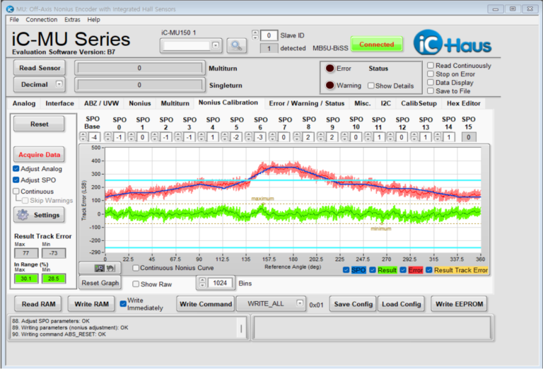
3.2 Technical Deep Dive: The IC-Haus iC-MU Series

The iC-MU series (comprising iC-MU, iC-MU150, and iC-MU200) consists of single-chip Hall magnetic encoder solutions designed for off-axis (hollow-shaft) and linear absolute position measurement.
These chips utilize a dual-track (Nonius/Vernier) scanning principle to provide high-resolution absolute data without processing delays.
The following table summarizes the primary technical parameters critical for application-end design:
Parameter | iC-MU | iC-MU150 | iC-MU200 |
|---|---|---|---|
Scanning Type | Off-Axis / Linear | Off-Axis / Linear | Off-Axis / Linear |
Master Pole Width | ~1.28 mm | 1.50 mm | 2.00 mm |
Absolute Resolution | 18-bit | Up to 20-bit (at 64 pole pairs) | Up to 20-bit (at 64 pole pairs) |
Max. Rotary Speed | 24,000 RPM | Up to 12,000 RPM | Up to 24,000 RPM |
Max. Linear Speed | 16 m/s | 16 m/s | 16 m/s |
Absolute Interfaces | BiSS C, SSI, SPI | BiSS, SSI, SPI | BiSS, SSI, SPI |
Incremental Outputs | ABZ, UVW | ABZ, UVW | ABZ, UVW |
FlexCount® Logic | Yes (arbitrary CPR) | Yes (1 to 65,536 CPR) | Yes (1 to 65,536 CPR) |
Supply Voltage | 5 V | 5 V | 5 V |
Operating Temp. | -40°C to +110°C | -40°C to +125°C | -40°C to +125°C (Tj up to 140°C) |
Package Options | DFN16 (5×5 mm) | DFN16 (5×5 mm), QFN48 (7×7 mm) | QFN48 (7×7 mm) |
- Dual-Track Principle: The system uses two tracks with slightly different pole counts (e.g., 32/31) to calculate absolute position within one revolution instantly upon power-up.
- Magnetic Target Matching: Each chip is specifically optimized for its namesake pole width (1.28mm, 1.50mm, or 2.00mm). Choosing a magnetic target with the correct pole width is essential for achieving the rated accuracy.
- Interference Immunity: The series utilizes differential field scanning, providing high immunity to external electromagnetic interference and magnetic stray fields.
- Multiturn Capability: These singleturn absolute chips can be synchronized with battery-buffered multiturn sensors (such as iC-PVL) to track revolutions even during power-off states
4. OTV's Magnetic Encoder Targets for the IC-Haus MU Series
We specialize in developing high-performance magnetic encoder discs and rings that are perfectly matched to the IC-Haus MU series of encoder chips, including the iC-MU, iC-MU150, and iC-MU200.
Our multipole encoder rings are engineered for precision and consistency.
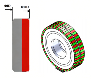
Here is our standard encoder discs for Axial and Radial detaction:
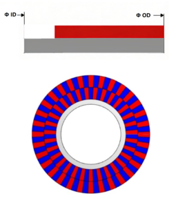
| AXIAL NONIUS ENCODER DISC | ||||||||
| IC MU200 | ||||||||
| Reference | Number of pole pairs on master track | Number of pole pairs on Nonius track | ID | OD | Diameter of master track | Diameter of Nonius track | Pole width of master track | Pole width of Nonius track |
| A2003200 | 32 | 31 | 25mm | 44.5mm | 40.8mm | 32.8mm | 2mm | 1.66mm |
| A2006400 | 64 | 63 | 62mm | 85mm | 81.5mm | 73.5mm | 2mm | 1.83mm |
| IC MU150 | ||||||||
| Reference | Number of pole pairs on master track | Number of pole pairs on Nonius track | ID | OD | Diameter of master track | Diameter of Nonius track | Pole width of master track | Pole width of Nonius track |
| A1503200 | 32 | 31 | 18 | 34.5 | 30.6 | 23.4 | 1.5 | 1.34 |
| A1506400 | 64 | 63 | 47,40 | 65,10 | 61.1 | 53.9 | 1.5 | 1.34 |
| IC MU | ||||||||
| Reference | Number of pole pairs on master track | Number of pole pairs on Nonius track | ID | OD | Diameter of master track | Diameter of Nonius track | Pole width of master track | Pole width of Nonius track |
| A1286400 | 64 | 63 | 38 | 56 | 52.2 | 45 | 1.28 | 1.12 |
| A1283200 | 32 | 31 | 15 | 29 | 26 | 18.88 | 1.28 | 1.12 |
| Radial NONIUS ENCODER DISC | ||||||||
| IC MU | ||||||||
| Reference | Number of pole pairs on master track | Number of pole pairs on Nonius track | D1 | D2 | Diameter of master track | Diameter of Nonius track | Pole width of master track/° | Pole width of Nonius track/° |
| R1286000 | 32 | 31 | 20 | 24.5 | 4.8 | 1.2 | 5.63 | 5.81 |
| IC MU150 | ||||||||
| Reference | Number of pole pairs on master track | Number of pole pairs on Nonius track | D1 | D2 | Diameter of master track | Diameter of Nonius track | Pole width of master track/° | Pole width of Nonius track/° |
| R1503000 | 64 | 63 | 53.1 | 59.6 | 5.8 | 2.2 | 2.81 | 2.86 |
Customization Services
OTV offers full customization:
Dimensions: We can redesign the outer diameter, inner diameter, and thickness to meet your mechanical requirement.
Pole Count: Need 16, 64, or even 128 pole pairs? We can do it.
Magnetization Direction: Choose radial or axial to suit your assembly.
Track Design: Single-track, dual-track, or with special reference marks.
Mounting Features: We can integrate the ring with custom metal backplates or hubs designed for your specific assembly housing.
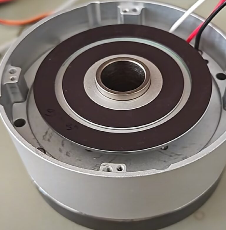
Application Example: Cobot Joint Feedback
-1-300x202.png)
The Challenge:
A leading collaborative robot manufacturer was developing a new 7-axis arm. They needed a compact joint module with a hollow bore for cabling. The feedback system had to achieve better than ±0.1° accuracy and operate reliably from -20°C to +80°C. They needed a high-performance off-axis absolute encoder solution with a reliable magnetic encoder disc.
The Solution:
To meet the client’s spatial requirements, our engineering team developed a fully custom, reduced-diameter magnetic encoder ring. Rather than altering the critical pole width, we strategically reduced the total number of poles on the ring. By keeping the pole width fixed at 1.28 mm—the precise specification required by the iC-MU chip—we ensured that the magnetic field geometry remained optimal for signal integrity. This approach resulted in a smaller ring that fits perfectly within the confined space without sacrificing the high-resolution performance required for precise servo control, delivering a drop-in magnetic target solution fully matched to the customer’s electronics and mechanics.
As a specialist in magnetic components, OTV is committed to providing high-quality, perfectly matched magnetic encoder discs and multipole rings for leading encoder chips like the IC-Haus MU series.
We’re not just a supplier; we want to be your engineering partner for custom solutions.
If you’re developing a new robotic joint or motor feedback system and need an off-axis absolute encoder solution, let’s talk. Our team is ready to listen to your specific requirements—your chip choice, your mechanical constraints, your accuracy goals—and recommend the optimal magnetic encoder disc for your application.. We’ll work with you to deliver a precision magnetic sensing solution:
- Standard magnetic ring
- Custom design magnetic ring
FAQ
1: What exactly is an off-axis absolute magnetic encoder?
A: It’s a system where the encoder IC is positioned to the side of a magnetic ring, rather than directly above the shaft’s center. This creates a hollow bore. By sensing the multi-pole magnetic pattern on the ring, it provides a unique absolute position immediately upon power-up, with no need for a battery or a homing sequence.
2.How well do OTV's magnetic rings work with IC-Haus chips?
A: Our magnetic rings are specifically engineered to complement the IC-Haus MU family (iC-MU, iC-MU150, iC-MU200, iC-MUE). We offer standard products with the correct pole widths (1.28mm and 2.00mm) and can fully customize pole counts, dimensions, and magnetization patterns to ensure your chip performs at its absolute best.
3.What is the standard MOQ for your magnetic rings?
We are flexible to discuss volume-based adjustments for prototype or trial orders.
4.Can you produce custom desgin samples before full production? Is there a charge?
Yes, we can provide custom designsamples for validation. Samples are typically charged at a nominal fee to cover material and setup costs. Lead time for sample building is generally 4 weeks after design confirmation.
5.What is the typical lead time for standard magnetic ring orders?
For standard products with no stock, the lead time is 2 weeks after order confirmation and receipt of deposit.
6.Can I request custom magnetic ring specifications?
Yes,we fully support customization for parameters such as inner/outer diameter, mounting hole positions, thickness, and magnetic properties to meet specific application needs.