Precision Encoder Magnetic Rings for Robotic Joint Modules

Picture this:
A surgical robot performing minimally invasive surgery, its arm moving with fluid precision around the finest blood vessels to reach its target. Or a high-speed robotic arm on an automotive assembly line, executing complex motions multiple times per second with millimeter-level repeatability, year after year.
Now, imagine humanoid robots learning to navigate parkour courses, their joints absorbing impacts several times their body weight while maintaining precise posture control.
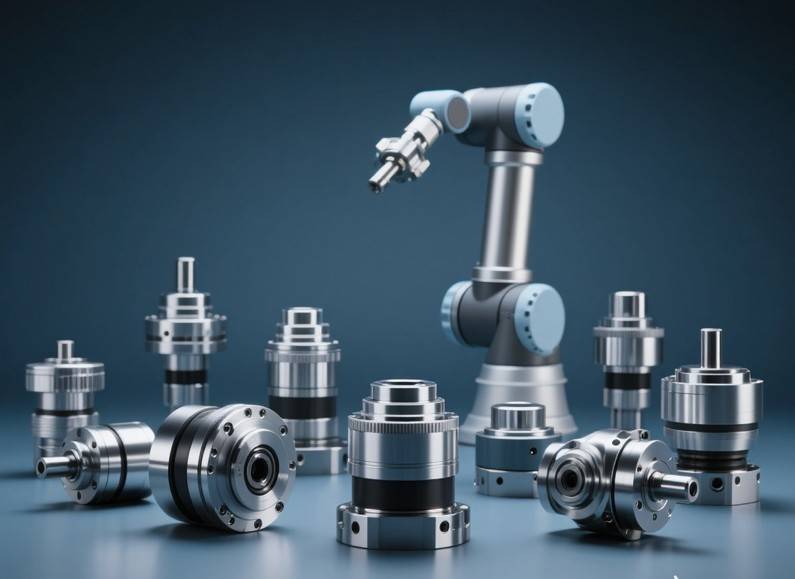
These modules convert the rotary or linear motion of a motor into articulated action, directly determining a robot’s capability to walk, manipulate, or interact. A single humanoid robot typically requires 30-40 such modules, employing different solutions for various joints: rotary actuators for shoulders and hips, linear actuators for knees and ankles. In many ways, the performance and cost of these modules define the performance and competitiveness of the entire humanoid robot.
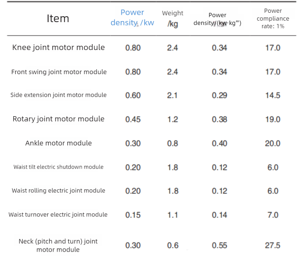
However, current joint motor modules face significant challenges, primarily in three areas: high self-weight, low power density, and relatively low torque density. The substantial weight of individual modules, combined with the large quantity required, leads directly to an overweight and costly final robot. For example, in some existing humanoid robots with 41 degrees of freedom (requiring 41 joint modules), these modules can account for 50-60% of the total robot mass and a staggering 60-70% of its cost.
Since humanoids must work against their own gravity, the industry consensus points to a required rated power density of at least 2.0 kW/kg. Current mainstream products, however, show a significant performance gap against this benchmark.
To address the critical needs of weight reduction and performance optimization, novel motor structures for direct-drive joint modules are emerging, such as frameless torque motors and coreless (hollow-cup) motors. Particularly groundbreaking is the integration of coaxial magnetic gear technology with permanent magnet motors, leading to the development of highly compact magnetic gear motors.
Direct-Drive Joint Modules
Direct-drive modules employ a highly integrated design, eliminating traditional gear reducers by deeply combining a frameless torque motor, drive electronics, encoder, brake, and often a torque sensor. Take the RJS series from a leading brand as an example: with the motor connected directly to the load, its compact design allows for a diameter under 90mm and a weight of just 1.75kg, dramatically reducing joint mass. Another brand’s RGM module utilizes a hollow shaft and an L-shaped housing, facilitating internal cable routing while improving spatial efficiency and ease of installation in collaborative robots.
1. Performance Parameters
The core advantages of direct-drive solutions are high dynamic response, ultra-low noise, and backlash-free transmission. One brand’s direct-drive motor achieves a remarkably low cogging torque of 1.2 mNm (peak-to-peak) and a torque constant of 0.227 Nm/A, enabling millisecond-level response times. The RGM14 module delivers a peak torque of 13.5 Nm at 35 RPM, providing excellent positioning accuracy for collaborative robots under 10kg payload. However, direct-drive solutions face a physical upper limit in torque density. For instance, the RJS14 offers a maximum instantaneous torque of 54 Nm, which, while impressive, still falls short of the hundreds of Nm achievable with geared solutions.
2. The Critical Role of High-Precision Position Feedback
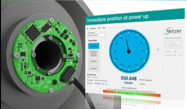
Direct-drive architecture places extreme demands on the position sensor (encoder). The encoder must provide ultra-high resolution, multi-turn absolute position feedback, and exceptional noise immunity. It must measure the motor rotor position directly and with high precision to enable accurate commutation for the brushless motor and closed-loop control. This precision is vital for maintaining positional accuracy, especially when compensating for the inherent torque limitations of the direct-drive approach. Our company’s high-precision magnetic ring encoder solution, with its excellent temperature stability and resistance to external magnetic interference, can deliver absolute position measurement accuracy of <0.01° for direct-drive joints. This ensures precise end-effector positioning and smooth, controlled motion.
Magnetic Encoders in Joint Modules
The position encoder within a joint module acts as its “nervous system” – the component that makes it “intelligent,” enabling it to perceive its own position and speed.
When selecting an encoding solution for a next-generation joint module, engineers typically evaluate two mainstream technological paths: magnetic encoders and inductive encoders. Both have their proponents.
Magnetic Encoder vs. Inductive Encoder
Magnetic Encoder vs. Inductive Encoder
| Feature Dimension | Magnetic Encoder (Based on Precision Magnetic Ring) | Inductive Encoder |
|---|---|---|
| Working Principle | Detects changes in the magnetic field from a permanent magnet ring. | Detects changes in electromagnetic coupling between PCB coils. |
| Core Components | Magnetic Ring + Hall/Magnetoresistive Sensor ASIC | PCB Rotor + Stator Boards |
| Accuracy & Resolution | • High-resolution achievable with multi-pole rings. • Dependent on ring quality & signal processing. | • Capable of extremely high resolution & accuracy. |
| Environmental Robustness | • Non-contact, fully solid-state. • Resistant to dust, oil, condensation. • High shock & vibration resistance. | • Insensitive to contamination. • Sensitive to mechanical air gap/alignment. |
| Temperature Stability | ⚠️ Requires attention (but manageable). • Magnet strength drifts with temperature. • Mitigated via high-performance materials (e.g., low-temp-coefficient SmCo) & compensation algorithms. | • Performance largely unaffected by temperature. |
| EMI Immunity | • Can be affected by strong external magnetic fields. • Mitigated via shielding, differential signals, and high-SNR rings. | • Highly immune to external static/dynamic magnetic fields. |
| Integration Friendliness | • Small, lightweight ring. • Enables hollow-shaft & compact designs. • More forgiving installation tolerances. | ⚠️ Demanding. • Sensitive to axial/radial alignment. • Longer lead times for custom PCBAs. |
If your joint module design seeks the optimal balance between reliability, cost, compactness, environmental tolerance, and sufficiently high accuracy – which is the core requirement for the vast majority of collaborative robots, industrial arms, AGV drive wheels, and special service robots – then a magnetic encoder based on a high-performance magnetic ring is often the superior, more pragmatic choice.
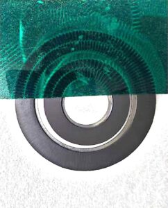
Today, let’s focus not on the complex control system, but on the frequently overlooked physical core component that largely determines the performance of the magnetic encoder itself: the Encoder Magnetic Ring.
This ring is the source of the motion feedback chain, the starting point where physical movement in the analog world is translated into precise digital understanding. Its quality directly determines whether your joint module is merely “adequate” or truly “exceptional.”
Our Magnetic Ring Solution Portfolio
Application Scenario: Collaborative Robot Joints, Miniature Servo Actuators.
Product Requirements:
High precision in magnetic pole geometry.
Exceptional consistency in magnetic field strength across all poles.
Minimized product thickness and overall dimensions.
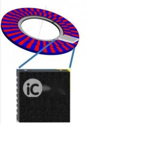
We offer standard magnetic rings compatible with leading encoder ICs, such as the iC-Haus IC-MU series.
| IC MU200 | ||||||||
| Reference | Number of pole pairs on master track | Number of pole pairs on Nonius track | ID2 | OD | Diameter of master track | Diameter of Nonius track | Pole width of master track | Pole width of Nonius track |
| A2003200 | 32 | 31 | 25mm | 44.5mm | 40.8mm | 32.8mm | 2mm | 1.66mm |
| A2006400 | 64 | 63 | 62mm | 85mm | 81.5mm | 73.5mm | 2mm | 1.83mm |
| IC MU150 | ||||||||
| Reference | Number of pole pairs on master track | Number of pole pairs on Nonius track | ID2 | OD | Diameter of master track | Diameter of Nonius track | Pole width of master track | Pole width of Nonius track |
| A1503200 | 32 | 31 | 18 | 34.5 | 30.6 | 23.4 | 1.5 | 1.34 |
| A1506400 | 64 | 63 | 47,40 | 65,10 | 61.1 | 53.9 | 1.5 | 1.34 |
| IC MU | ||||||||
| Reference | Number of pole pairs on master track | Number of pole pairs on Nonius track | ID2 | OD | Diameter of master track | Diameter of Nonius track | Pole width of master track | Pole width of Nonius track |
| A1286400 | 64 | 63 | 38 | 56 | 52.2 | 45 | 1.28 | 1.12 |
| A1283200 | 32 | 31 | 15 | 29 | 26 | 18.88 | 1.28 | 1.12 |
From Design to Mass Production: Customizing Your Magnetic Ring
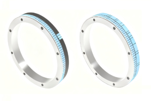
Beyond standard products, we provide fully customized magnetic ring solutions to meet specific installation, spatial, and IC compatibility requirements.
Co-Design & Rapid Prototyping: Share your installation space constraints, performance targets, and IC selection with us. Our engineers will engage in the early design phase, providing ring selection and design recommendations, and deliver functional prototypes for testing within 2-4 weeks.
Seamless Ramp-to-Production: Once the prototype is approved, our mature supply chain and manufacturing systems ensure a swift transition to volume production while maintaining high consistency from engineering samples to mass-produced units.
We are ready to collaborate with you to explore how we can design and manufacture the most suitable and reliable magnetic ring product for your specific application.
FAQ
1.What output resolution can be achieved with the IC-MU200?
Depending on the number of master pole pairs (16, 32, or 64) of the matched magnetic ring, the IC-MU200 can provide output signals with 18, 19, or 20 bits of resolution.
2.What are the specific requirements for magnetic rings in direct-drive joints?
They must be thinner and smaller to fit compact spaces, use low-temperature-coefficient materials to withstand internal motor heat, and maintain signal stability in high electromagnetic interference environments.
3.What is the standard MOQ for your magnetic rings?
We are flexible to discuss volume-based adjustments for prototype or trial orders.
4.Can you produce custom desgin samples before full production? Is there a charge?
Yes, we can provide custom designsamples for validation. Samples are typically charged at a nominal fee to cover material and setup costs. Lead time for sample building is generally 4 weeks after design confirmation.
5.What is the typical lead time for standard magnetic ring orders?
For standard products with no stock, the lead time is 2 weeks after order confirmation and receipt of deposit.
6.Can I request custom magnetic ring specifications?
Yes,we fully support customization for parameters such as inner/outer diameter, mounting hole positions, thickness, and magnetic properties to meet specific application needs.