Hard Ferrite Magnetic Rings in Magnetic Encoder Application: Performance and Key Parameters
In the rapidly evolving landscape of industrial automation, robotics, and automotive electronics, magnetic encoders have emerged as a dominant technology for displacement and angular sensing. Their popularity stems from their non-contact measurement, high environmental durability (IP67+ potential), and flexible integration.
The performance of any magnetic encoder system hinges on two pillars: the magnetic sensor IC (Hall-effect or Magnetoresistive) and the Multi-pole Magnetic Ring. Among various materials, Sintered Ferrite remains the industry standard for high-precision applications due to its unparalleled thermal stability and cost-efficiency.
Manufacturing Process: From Powder to Precision Magnet

The production of hard ferrite magnets for encoders requires a sophisticated powder metallurgy process to achieve the necessary magnetic consistency and mechanical tolerances.
Step 1: Calcination & Chemical Formulation
The process begins by mixing iron oxide with strontium or barium carbonates. High-temperature calcination ($1000°C$ to $1350°C$) creates the hexagonal crystal structure essential for permanent magnetic properties.
Step 2: Micron-Level Milling
Pre-fired material is milled into a fine powder (0.8–1.2 microns). This particle size is critical for optimizing the Residual Induction ($B_r$) during the alignment phase.
Step 3: Anisotropic Wet Pressing (Molding)
To achieve superior Maximum Energy Product ($(BH)_{max}$), we utilize anisotropic molding. By applying a powerful external magnetic field during the wet-pressing stage, we align the magnetic domains, ensuring the ring delivers maximum signal strength.
Step 4: Sintering & Diamond Grinding
The “green” magnets are sintered at ultra-high temperatures to create a dense, ceramic-like body. Given the high shrinkage rates, precision diamond grinding is employed to meet micron-level geometric tolerances for OD, ID, and concentricity.
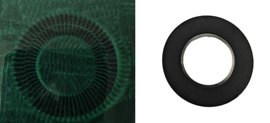
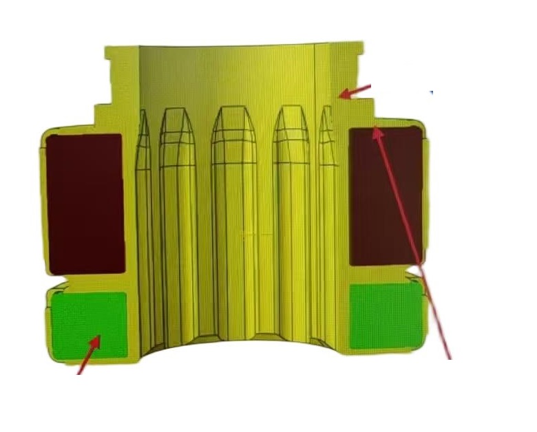
Step 5: Multi-Pole Magnetization
Using custom-engineered fixtures, we magnetize specific N/S pole pairs (e.g., 64-pole, 128-pole, or Nonius/Vernier tracks for absolute encoders) onto the ring’s circumference.
The IC-MU200 can be applied in absolute linear displacement sensing, and the magnetic scale matched with it can be customized according to specific application requirements, such as:
Magnetic Pole Width: 2 mm
Dual-Track Magnetization: Requires a master track and a nonius track
Customizable Support Structure: Can be designed to meet mechanical integration requirement
2. Performance Comparison: Ferrite vs. NdFeB vs. Magnetic Rubber
Choosing the right magnetic material for encoders involves balancing magnetic flux, temperature resistance, and budget.
| Feature | Sintered Ferrite | Neodymium (NdFeB) | Magnetic Rubber |
| Remanence ($B_r$) | 0.2 – 0.4 T | 1.0 – 1.4 T | 0.1 – 0.2 T |
| Coercivity ($H_{cj}$) | High | Very High | Low |
| Temp. Stability | Excellent (up to 250°C) | Moderate (80-200°C) | Low |
| Corrosion Resistance | Inherent (No coating) | Poor (Requires Plating) | Good |
| System Cost | Highly Competitive | High | Medium |
The Ferrite Advantage in Industrial Sensors
Zero Corrosion: Unlike Neodymium, Ferrite is an oxide and will not rust in high-humidity or salt-spray environments.
Positive Coercivity Coefficient: Unique to Ferrite, its resistance to demagnetization actually increases as temperature rises.
Cost-to-Precision Ratio: Ideal for high-volume servo motor and robot joint production.
3. Key Design Parameters for Magnetic Encoder Integration
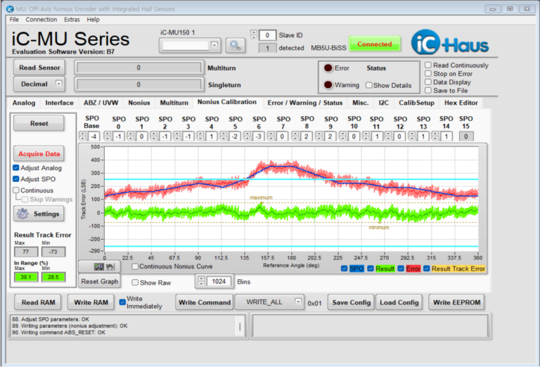
To ensure signal integrity and system resolution (reaching up to 21-bit absolute positioning), engineers must focus on these critical factors:
Pole Pitch Accuracy: Crucial for minimizing Non-Linearity Errors (INL).
Operating Air Gap: Typically optimized between $0.4mm$ and $1.0mm$. Our ferrite rings provide a consistent $20mT$ to $80mT$ surface field for reliable IC triggering.
Track Configuration: Supporting both Incremental and Absolute (Dual-track) designs for real-time position memory.
4. Typical Specifications: Hard Ferrite Magnetic Rings
| Parameter Category | Technical Specification | Typical Range |
| Magnetic Specs | Residual Induction ($B_r$) | 380 – 410 mT |
| Max Energy Product ($(BH)_{max}$) | 26 – 32 kJ/m³ | |
| Reliability | Operating Temperature | -40°C to +250°C |
| Electrical Resistivity | > 10⁶ Ω·cm |
OTV for Custom Magnetic Solutions
The ferrite magnetic ring is the “signal carrier” of the encoder system. While rare-earth magnets like NdFeB offer higher magnetic density, ferrite magnet remains the dominant choice for mainstream industrial applications due to its chemical inertness, wide temperature range, and cost-effectiveness.
As high-integration sensor chips from companies like iC-Haus continue to improve their error-compensation and signal-processing capabilities, ferrite-based absolute encoders can now achieve remarkably high resolutions (up to 17–21 bits). This makes them ideal for the demanding requirements of collaborative robot joints and precision servo motors.
Ferrite magnetic materials are hard but have high brittleness, exhibiting poor impact and tensile resistance, making them prone to cracking or fracturing under external force.
To address this issue, a rubber bonding magnet (magnetic rubber) solution was developed: ferrite magnetic powder is mixed with polymer materials such as rubber (e.g., nitrile rubber) and processed through calendering or injection molding. Products made with this method combine magnetic properties with the flexibility of rubber.
Why Choose OTV?
Custom Multi-Pole Magnetization: Tailored pole counts for specific resolutions.
Engineering Support: We help you optimize the air gap and magnetic field distribution for your specific sensor IC.
Quality Consistency: Strict ISO-grade control over sintered ceramic uniformity.
Ready to optimize your sensor performance? [Contact OTV today] to discuss your technical requirements with our application engineers. Let’s collaborate to build more reliable, precise, and cost-effective motion control systems.
FAQ
1.What output resolution can be achieved with the IC-MU200?
Depending on the number of master pole pairs (16, 32, or 64) of the matched magnetic ring, the IC-MU200 can provide output signals with 18, 19, or 20 bits of resolution.
2.Are the standard magnetic rings only suitable for angle measurement?
The IC-MU200 chip can be used for both absolute angle measurement and absolute linear displacement measurement. Linear magnetic scale need to be used for linear absolute position measurement.
3.What is the standard MOQ for your magnetic rings?
We are flexible to discuss volume-based adjustments for prototype or trial orders.
4.Can you produce custom desgin samples before full production? Is there a charge?
Yes, we can provide custom designsamples for validation. Samples are typically charged at a nominal fee to cover material and setup costs. Lead time for sample building is generally 4 weeks after design confirmation.
5.What is the typical lead time for standard magnetic ring orders?
For standard products with no stock, the lead time is 2 weeks after order confirmation and receipt of deposit.
6.Can I request custom magnetic ring specifications?
Yes,we fully support customization for parameters such as inner/outer diameter, mounting hole positions, thickness, and magnetic properties to meet specific application needs.