1. What is a Magnetic Encoder Ring?
An encoder is a sensing system that converts mechanical displacement (angle/position/speed) into electrical signals. It’s widely used in industrial automation, robotics, motor control, and medical devices.
Encoders can be classified based on their working principles:
| Encoder Type | Working Principle | Key Characteristics |
|---|---|---|
| Optical Encoder | Uses a grating and photoelectric sensor to detect light signal changes | High resolution, high precision, sensitive to contamination |
| Magnetic Encoder | Uses a magnetic ring’s field variation, detected by a magnetic sensor | Contamination-resistant, non-contact, high reliability |
| Inductive Encoder | Detects position change based on electromagnetic induction | Strong interference immunity, no magnetic materials needed |
You should consider a magnetic encoder in the following scenarios:
| Application Scenario | System Conditions / Requirements | Why a Magnetic Encoder Fits | Typical Industry Use |
|---|---|---|---|
| Harsh Environments | Dust, oil, moisture, condensation | No optical path, unaffected by contamination | Industrial Automation, Heavy Machinery |
| Space-Constrained | Limited axial or radial space | Compact ring structure, easy integration | Compact Motors, Robot Joints |
| High Reliability Needs | Long continuous operation, difficult maintenance | Non-contact, no wear, long lifespan | Industrial Equipment, AGV/AMR |
| Larger Mechanical Tolerances | Eccentricity, runout, installation error | High tolerance to mechanical errors | Mass-Produced Equipment, Complex Assemblies |
| Customization Required | Non-standard structure, special pole count | Ring and magnetization can be customized | Custom Motors, Special Actuators |
| High Consistency Needs | Mass production, stable output | Controllable magnetic field, good consistency | Industrial Robots, Automated Lines |
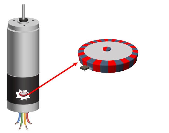
A magnetic encoder typically consists of: a PCBA with the magnetic encoder chip at its core + the magnetic encoder ring + the mechanical housing.
Magnetic encoder chips can be categorized by principle: Hall, AMR, TMR, etc.
You should consider a magnetic encoder in the following scenarios:
| Application Scenario | System Conditions / Requirements | Why Magnetic Encoder Fits | Typical Industry Use Cases |
|---|---|---|---|
| Harsh Environments | Dust, oil, moisture, condensation | No optical path, resistant to contamination, high stability | Construction machinery positioning, motor feedback in food production lines |
| Space-Constrained | Limited axial/radial installation space | Thin-ring design, can be embedded into compact structures, high integration | Robotic joint motors, UAV gimbal motors |
| High-Reliability Needs | Long continuous operation, minimal maintenance windows | Non-contact, no wear, lifespan >100,000 hours, maintenance-free | AGVs in automated warehouses, wind turbine pitch systems |
| Wide Tolerance Applications | Installation eccentricity (>0.5mm) or shaft runout | Tolerant to air gap variations, strong magnetic field adaptability | Batch assembly of home appliance motors, industrial pump/valve control |
| Customization Required | Non-standard mounting interfaces, special pole pairs, or index signal needs | Customizable ring size/poles/index position to match mechanical designs | Medical device motors, aerospace actuators |
| High Consistency Needs | Mass production with output signal error <±1% | Consistent magnetization in batch production (deviation <0.3°) | New energy vehicle motors, servo motor mass production |
Magnetic Encoder System Components
▸ Sensing Core: Magnetic Encoder Chip (Hall/AMR/TMR supported)
▸ Magnetic Source: Customized Magnetic Target (material/size/poles configurable)
▸ Integration Carrier: PCBA + Mechanical Housing (adaptable to customer mounting interfaces)
Typical Structure of a Rubber Magnet Taget:


2.Why Do You Need a Custom Magnetic Target?
In industrial and robotics applications, the performance of a magnetic encoder sensing system—its accuracy, repeatability, etc.—is determined by the combined interplay of the magnetic encoder chip, the magnetic target, and the mechanical installation.
If any one of these elements changes (the chip, mounting method, or spatial constraints), an off-the-shelf ring often won’t meet your specific application’s demands.
Common constraints in real-world industrial and robotics applications include:
Restricted installation space
Need for an added reference mark
Tolerances in concentricity and runout
High-speed or high-vibration operation
Special mounting/fastening methods
By customizing the taget’s dimensions, tolerances, mounting features, and magnetization pattern, you can tailor the entire magnetic encoder system to fit your specific application perfectly. This enhances overall system precision and reliability.
3. Multi-Pole Magnet Encoder Targets
A multi-pole magnetic target is magnetized circumferentially with multiple alternating N/S poles. Increasing the number of poles enhances the magnetic field’s spatial resolution, which significantly boosts the sensing system’s output resolution. Multi-pole target are ideal for industrial servo systems and robot joints requiring continuous, high-precision angular feedback. Parameters like pole-pair number can be customized based on your chip’s capabilities and system requirements to strike the optimal balance between resolution, signal stability, and cost. Multi-pole rings can be categorized by their magnetization tracks:
- Single-Track Multi-Pole Target
- Single-Track Multi-Pole Target with Reference Mark: Enables single-turn absolute positioning by incorporating a dedicated reference point on the ring.
- 2-Track Multi-Pole Target: Provides a unique absolute position through vernier calculation.


3.1 Radial Magnetization Encoder Ring
-1.png)
Radial Magnetization means the magnetic field is oriented along the radius direction. It’s one of the most common magnetization methods for shaft-mounted encoder systems. This configuration creates a stable, symmetrical field at the ring’s outer or inner diameter, making it perfectly suited for use with surrounding magnetic sensor ICs.
In industrial motors and robot joints, radially magnetized rings effectively reduce sensitivity to air gap variations, improving the overall system’s robustness.
3.2 Axial Magnetization Encoder Ring

In Axial Magnetization, the magnetic field is oriented along the axis. This type is typically used in space-constrained designs or for end-face detection structures. Compared to radial magnetization, axial magnetization is better suited for compact form factors.
In robot end-effectors, compact servo modules, or integrated encoders, axially magnetized rings enable reliable angle detection within limited axial space.
We offer standard magnetic rings compatible with the IC HAUS MU series chips such as MU, MU150, and MU200. Additionally, we can customize magnetic ring products according to customers’ specific requirements to meet the demands of the chips.
3.3 Linear Magnetization Encoder Target

Magnetic encoders require the use of specialized linear magnetic scales to achieve high-precision linear displacement sensing, forming a closed-loop measurement system.
Depending on the specific measurement requirements, linear magnetic scales can be classified into two main types based on their encoding design:
- single-track linear magnetic scales
- dual-track linear magnetic scales
Common magnetization pitches include 1 mm, 2 mm, or 5 mm.
4. Manufacturing Process for Rubber Magnet Rings
Standard rubber magnet rings are produced by bonding a metal support ring with rubber compounded with ferrite powder. The assembled product is then magnetized using high-voltage pulse equipment to form a ring with a regular magnetic pole pattern.

Ferromagnetic rubber is a composite material that mixes ferrite powder with uncured rubber (such as nitrile rubber) and solidifies it through a vulcanization process. The main technical challenges lie in achieving uniform dispersion of the powder within the rubber matrix and maintaining a high filling rate of the ferrite powder.
-768x576.png)
Magnetization is another critical process in magnetic ring manufacturing, where high-voltage pulses are used to generate instantaneous strong magnetic fields to instantly magnetize the ferrite particles within the rubber.
The precision of magnetization is collectively determined by factors such as:
- the uniformity of the rubber mixture,
- the accuracy of the magnetization mold,
- the concentricity of the magnetization rotation mechanism.

100% of products must be measured before delivery to customers for the accuracy.
5. Typical Industrial Sensing Applications
Industrial Servo Motors
Robot Joints and Actuators
Position Feedback for Automated Equipment
Precision Rotary Control Systems


6. We Work For Your Custom Magnetic Encoder Ring
We can customize the following key parameters based on your specific magnetic encoder chip and mechanical installation:
- Number of Poles and width of pole pitch
- Magnetization direction (Radial / Axial)
- Special magnetization patterns
- Special reference marks (e.g., a missing pole)
- Magnetic field strength
- Encoder Ring dimension and tolerance (for instance, 1mm thickness for some application is required)
If you’re developing an industrial or robotic encoder sensing system, we hope to discuss with you for your magnetic encoder ring requirement. Our engineering team is ready to work with you for a suitable magnetization scheme and mechnical structure.
FAQ
When should you consider using a magnetic encoder?
Consider a magnetic encoder when your application involves dust, oil, moisture, or condensation, or when you have stringent requirements for installation space, mechanical tolerances, or long-term operational reliability. It’s particularly well-suited for industrial automation, robotics, and heavy machinery where compactness and durability are key.
Why might you need a custom magnetic encoder ring instead of a standard one?
Because encoder system performance depends on the combined effect of the ring, sensor chip, and mechanical housing. When installation space, mechanical tolerances, speed, or needed features (like a reference mark) fall outside standard product ranges, a custom ring lets you optimize dimensions, magnetization, and mounting to ensure peak system accuracy, stability, and reliability.
What key parameters can typically be adjusted when customizing a magnetic encoder ring?
Key customizable parameters include: pole-pair count and pitch, magnetization direction (radial/axial), magnetic field strength, precise ring dimensions and tolerances, mechanical mounting interfaces, and special features like the shape and location of a reference mark. These must be matched to your sensor’s characteristics and mechanical design.
What is the typical development and production timeline for a custom magnetic encoder ring?
The process typically has two phases. First, sample development (design, tooling, prototype fabrication) usually takes 4 to 8 weeks. Second, after sample approval, batch production and delivery for a standard order takes about 3 to 6 weeks. The total timeline depends on design complexity, magnetization process, and order quantity.
Is there a Minimum Order Quantity (MOQ) for custom rings?
We can provide prototype samples based on your actual initial quantity requirements. Please note that the cost for these initial samples will vary accordingly based on the specifications.
What are the key steps in a typical custom development process?
The main steps are:
1. Requirements Communication: Clarify all technical parameters (dimensions, pole count, operating environment, etc.).
2. Design & Confirmation: Provide drawings for mutual confirmation.
3. Sample Fabrication & Testing: Deliver physical samples and test reports.
4. Customer Validation: You test the samples in your system and provide feedback.
5. Batch Production & Delivery: Mass production and shipment according to the confirmed specifications.