I. Standard Cored Motor
The rotor of a standard DC motor is laminated from silicon steel sheets, and the windings are wound around an iron core. It has high inertia, high inductance, and a relatively slow response speed.
1. Requirements for Position Sensing:
- High Precision and Resolution: Many applications such as robotic joints and CNC machine tools require knowledge of the rotor’s absolute position and precise speed to achieve precise motion control.
- Low-Speed Performance: Stable torque must be provided even at low speeds or zero speed, which requires the sensor to provide high-quality position signals at low speeds.
- Reliability: Industrial environments require sensors to be rugged, durable, and have strong anti-interference capability.
2. Implementation Methods:
Position sensing in standard motors typically uses physical sensors mounted directly on the motor shaft.
- Optical Encoder:
- Principle: A light-emitting diode (LED) illuminates a code disc engraved with a precise grid. Light passes through or is blocked by the disc and is received by photoelectric sensors, generating pulse signals (Phase A, B). Position is obtained by counting pulses, speed by pulse frequency, and direction by the phase relationship between Phase A and B.
- Types: Divided into incremental (only knows relative displacement) and absolute (each position has a unique code that is not lost after power loss).
- Advantages: Extremely high accuracy, fast response.
- Disadvantages: Higher cost, sensitive to dust and contamination, relatively fragile structure.
- Magnetic Encoder:
- Principle: A magnet rotates with the rotor, and Hall sensors or magnetoresistive sensors detect the changes in the magnetic field to determine position.
- Advantages: Lower cost, rugged, durable, strong resistance to contamination.
- Disadvantages: Accuracy and resolution are usually lower than top-tier optical encoders, susceptible to external magnetic fields.
- Resolver:
- Principle: An analog position sensor that measures angle based on electromagnetic induction principle. The rotor winding acts as the excitation, and the stator windings output signals that have sine and cosine relationships with the angle.
- Advantages: Extremely rugged, high temperature resistant, radiation resistant, extremely strong anti-interference capability, very suitable for aerospace, military, and harsh industrial environments.
- Disadvantages: Complex system (requires an additional RDC circuit to convert analog signals to digital angles), high cost.
II. Coreless Motor (Cup Motor)
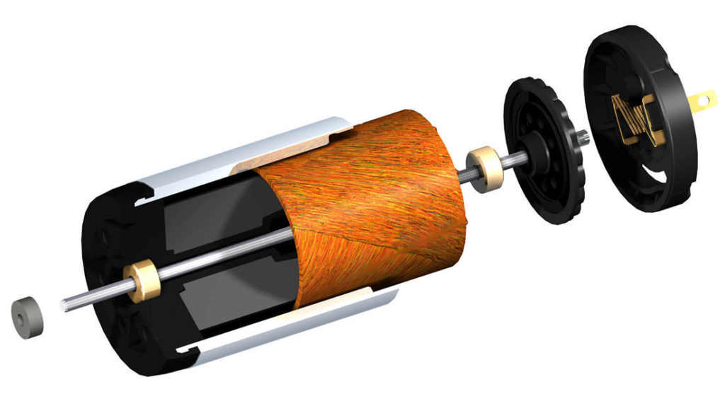
Unlike traditional motors, coreless motors do not rely on the traditional iron core rotor structure. Instead, they feature a novel coil construction that resembles a hollow cup. This unique design grants the motor characteristics like lightweight, high efficiency, precision, high speed, and small size, enabling many innovative motor applications.
The coreless motor rotor has no iron core and is a self-supporting winding “cup” structure. Its inertia and inductance are extremely low, and its response speed is very fast.
1. Requirements for Position Sensing:
- Extremely Low Inertia: This is the most critical point. Any physical sensor (e.g., encoder) added will increase the rotor’s moment of inertia, which directly negates the coreless motor’s biggest advantage – extremely fast response and high acceleration.
- Ultra-High Frequency Update: Due to its very small electrical time constant, the commutation frequency can be very high (far exceeding standard motors), requiring the control loop (including position detection) update rate to be equally high.
- Size Constraints: Many applications using coreless motors (e.g., drones, micro-robots, precision medical instruments) have extreme size requirements, leaving no space for additional sensors.
2. Implementation Methods:
Therefore, coreless motors use sensorless control schemes, and only in ultra-high precision requirement scenarios are micro-sensors used.
- Sensorless Control:
- Principle: Estimates rotor position by detecting the back EMF generated during motor operation. When the rotor rotates, the windings cut the magnetic flux lines, generating back EMF (BEMF), whose waveform is directly related to the rotor position. By detecting the voltage in the floating phase (the phase not energized), the algorithm estimates the current rotor position.
- Implementation Algorithm: The most mainstream method is Field-Oriented Control (FOC). FOC measures the motor’s phase currents and uses mathematical models (e.g., an observer) to estimate the rotor’s angle and speed in real-time, enabling precise torque and speed control.
- Advantages:
- Zero Added Inertia: Does not affect the motor’s dynamic performance at all.
- Zero Added Volume: Requires no external hardware; all calculations are done by the controller.
- Low Cost: Saves the cost of the sensor itself.
- Disadvantages:
- Startup Challenge: When the motor is stationary, the back EMF is zero, making position detection impossible. Special startup algorithms (e.g., “align and start”) are needed to forcibly pull the motor to a certain speed before switching to sensorless mode.
- Low-Speed Performance: At very low speeds, the back EMF signal is very weak and difficult to detect, potentially leading to reduced control performance or even loss of synchronization.
- Algorithm Complexity: Places high demands on processor computing power.
- Micro Encoders/Hall Sensors:
- In a少数 of applications where there are extremely high requirements for low-speed smoothness and starting torque, and slight inertia and volume increase can be tolerated (e.g., high-precision bionic robots, medical surgical instruments), ultra-small, ultra-lightweight optical or magnetic encoders are used.
- These sensors are specially designed, their inertia and volume are minimized, but the cost is very high.
Summary of Core Differences
| Characteristic | Standard Cored Motor | Coreless Motor |
|---|---|---|
| Core Need | High resolution, high precision absolute position/speed feedback | Ultra-high response speed, high-frequency real-time position estimation |
| Application Driver | Precise position control, low-speed smoothness, high starting torque | Extreme acceleration, very fast dynamic response, smooth low-speed operation |
| Common Solutions | Optical Encoder, Magnetic Encoder, Resolver | Sensorless algorithms (mainly FOC), micro encoders |
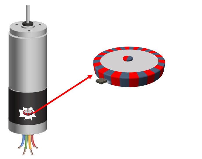
OTV Company can provide magnetic encoder sensing solutions compatible with both motor types.
Magnetic Encoder Chip Core Performance:
- Ultra-High Resolution
- Angle Measurement Resolution: 0.015°
- Digital Output Resolution: 16-bit
- Exceptional Accuracy and Stability
- Can maintain performance within a wide working magnetic field range of 15 – 150 mT
- Strong resistance to external magnetic field interference
- Extreme Dynamic Response
- Angle Update Rate: Up to 1 MHz
- Response Delay: Only 3 μs (during极限 acceleration/deceleration phases)
- Electrical Characteristics
- Operating Voltage: Supplies 3.3V and 5V power
- Power Consumption: 11.6 mA
- Strong Environmental Adaptability
- Operating Temperature Range: -40°C to +125°C
- High Integration and Compatibility
- Ultra-small QFN33 package, can be integrated into Φ<13mm微型 coreless motors
- Supports multiple mounting positions
- Flexible Output Interface
- Provides ABZ, UVW, SPI, PWM and other output interface options to adapt to different application scenarios.
- Matching Magnet Target
- We provide matching multi-pole magnet rings with high accuracy and stability, which can further improve and ensure the system’s measurement accuracy.